Hi everyone,
Someone could demonstrate as to create gridlines in inventor drawings?
Or someone has an app for this and could share?
Thanks in Advance.
Hi,
Sometimes our customers require these drawings to CMM department to check the dimensional of the weld fixtures (jigs). So, We need to put these gridline with your coordinates in the drawings.
Thanks.
Oh I see, allow me to ask a few more questions in order to help you because the thing is, Autodesk Inventor is a Manufacturing Software, it is a powerful tool but is not meant to be a coordination tool?! So, the creation of grid lines for coordination purposes is not part of Inventor however one more question what software your customers are using? Autodesk Revit, Revit Structure, Revit MEP something like that?
Im talking about construction Industry
Ok Now I'm curious, let me understand the process first:
Lets say you guys design something in Inventor, like an structure, or platform. Welds, plates, bolted connections, etc are added to this model and then you create the drawing. that drawings goes to your clients and then thy will check dimensions or interference or clash detection anddddd....i will assume using another software???
If this is correct this is a very interesting situation.
Yes, in welding fixtures we use all these components that you mentioned. we development weld fixtures to automakers. resistance welding, project welding, spot welding, mig welding, etc...
The drawings we need to send the customer are PDF and STEP. The automakers use CATIA always. But the gridline is much used to the quality and CMM department because they use this drawing to know the points needs to be measured.
I can draw the gridlines but this way manual the process stay late.
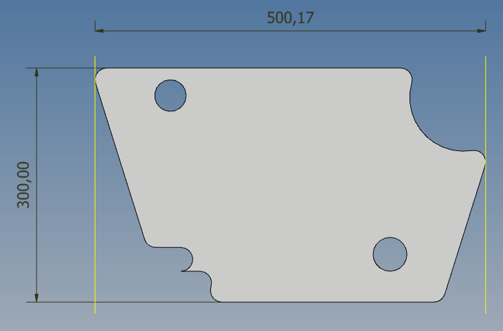
Below are images to better explain.
Thanks.
Hi
I know two apps for gridlines:
Unfortunately none of them seem to be free...
Can you explain your current workflow creating these gridlines?
Are the gridline labels always the same?
Is the positioning of the gridlines specific to some part or assembly workplane?
Maybe a ilogic rule could automate your current workflow.
Thanks.
Hi,
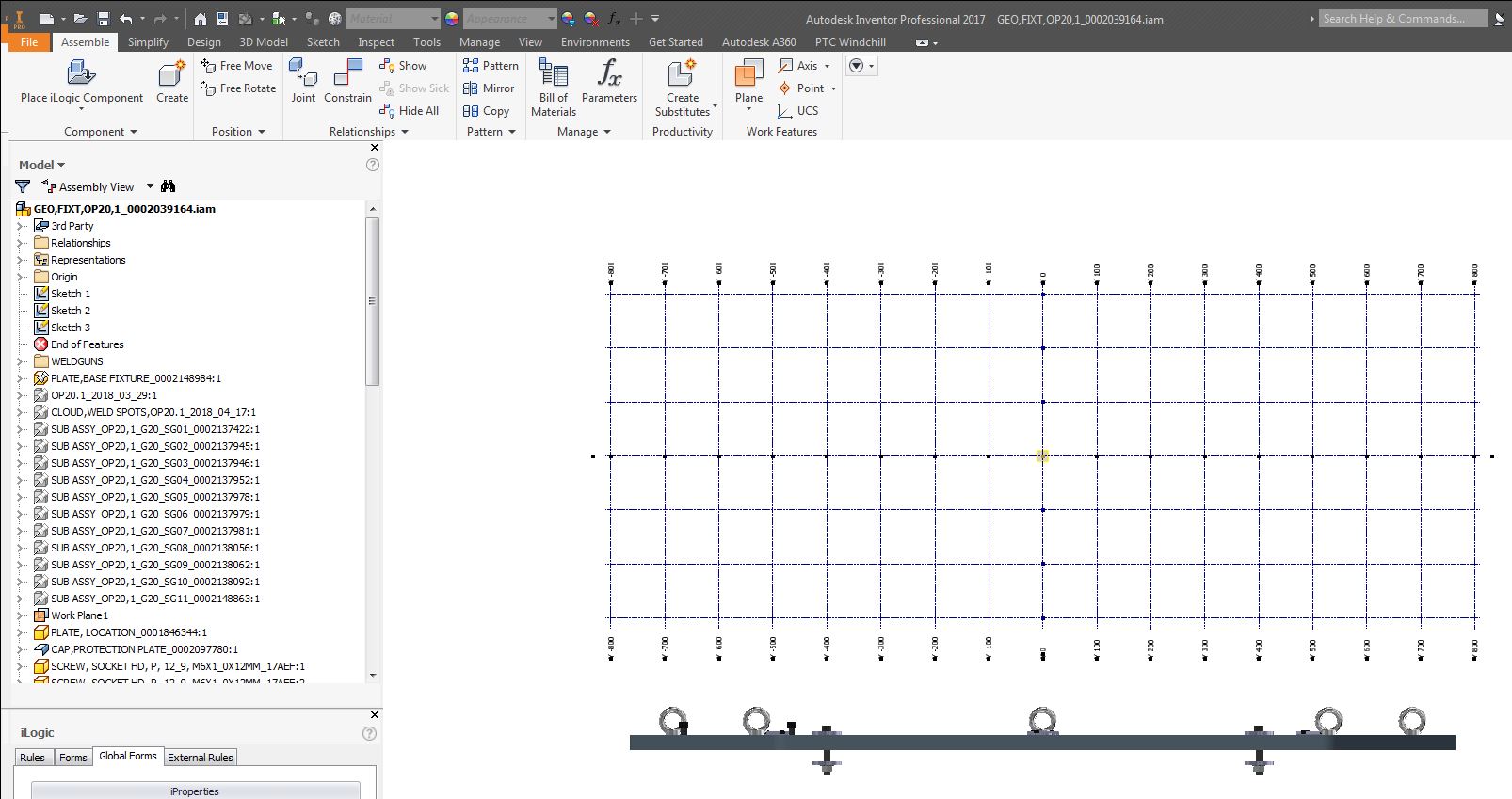
Currently, I create these gridlines through of the sketch in the 3D model being able to be part of the CAD part or CAD assembly.
Yes, the gridlines labels are the same always. These labels are the coordinates referring to the zero of the car and are differentiated for negative coordinates and positive coordinates.
So, I use the workplanes XYZ to create the gridlines.
I thought about that, but I don't have the knowledge to program a tool in iLogic. That is why I created this topic to be able to help me with this.
Below others image the gridlines.
Thanks in Advance.
My apologies by the delay in reply, I was returning from my annual leave yesterday so I,m getting into the mode of "long working hours" now. I,m very curious about this topic and very keen to help you. Certainly it is a good Idea to know about your workflow that's the only way to help you with your issue.
Please do not get me wrong and let me ask you more questions in order to get the things right.
1-When you say that the grid lines are always the same is because the distance between the lines (the increment) is always the same you only add more planes in one direction or another to suit the design???
If your answer is positive, it is probably the best, without going to something maybe more complicated, use the planes as you are, but with parameters, once that you create this save the file as a template and that's all. In that way you will have a part named (Dynamic_grid.ipt) that you can insert into the assembly. The grid will grow in all directions and you can constrain it perfectly in the assembly context.
I logic is a solution, is great, is perfect but honestly I think that you can solve this issue without Ilogic.
Hi P.Lopez,
No problem, I can't answer in real time too. :D
So, I will try answer your doubts... ;D
1) Yes, the distance between the lines is the same always, I usualy use 100mm of the increment.
2) The labels that are located at the end of the line are the coordinates from zero of the car. the image above show better it. The CMM department use these coordinates to orient yourself about the positions on the weld fixture.
3) yes, I only add more or less planes in all directions to suit in my design.
4) I work with windchill (PTC). So, I don't know if this is a problem in the creation the gridlines. This will be a feature or a sketch in the design?
Let me know if you have any doubts....
Thanks in Advance.
Hi Jose,
Thanks, so I will try to give you an Idea about how I will do it, I recon that if I had this situation before I could probably give you a better solution, however lets see what comes to my mind.
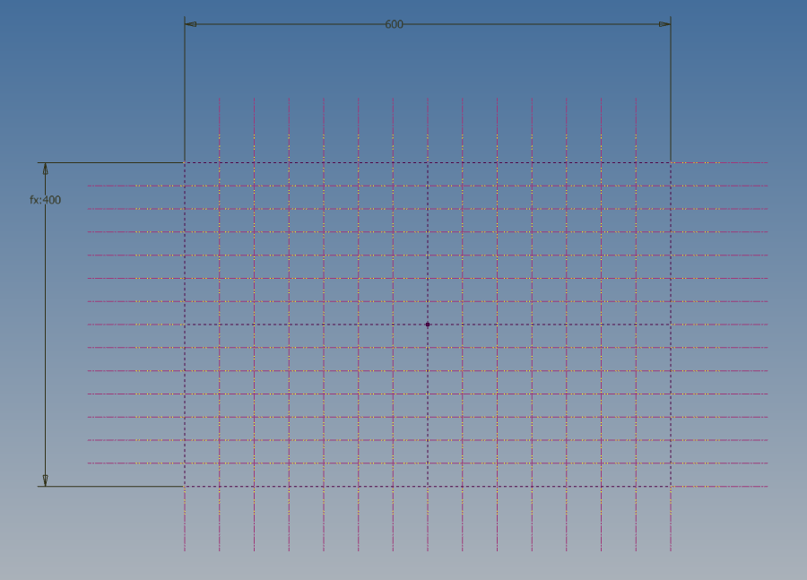
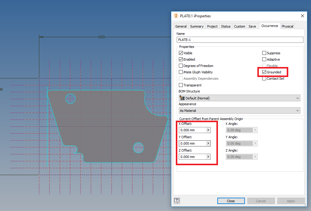
Obviously Im not using equal distance between grid lines Im adjusting the grid lines (axis) otherwise you will need a higher quantity of lines.
Please let me know how this idea work, if it doesn't, don't matter we will try to find another way.
Hope this help
The simplest way is to import an image of a graph chart with the required grids, numbering, Coordinate vectors, etc
and put it as a background, so your end product will not render too many faces and to focus your efforts on your model instead.
Regards,
That specific method depends of so many factors, and accuracy is quite important here because we are talking about building something not representing something.
The thing is, imported image comes normally from scanned documents, screen capture etc.
If the images comes from an scanned document how do you guarantee that the distance between lines is, effectively, lets say 100 mm??. IN the same way, when you scan an image of a grid line ("I will assume that's the easy way we are talking") every line will have a thickness when yo make a zoom that image because is compose by pixels (scanned images are a bitmap) there is a high probability that image gets out of precision, distortion will be present sometimes. So deal with images is in my opinion quite tricky and not quite precise. Now
There is topic in this aspect (Images and Vectors) Images can be Bitmap (scanned documents, any gif, jpg, bmp, etc but also can be a VECTOR. Vectors are a result from a mathematical calculation, we are talking about eps file extensions. Anything that comes from softwale like Adobe Illustrator, Corel Draw, CAD software thats the reason why lines in AutoCAD, INventor or any CAD soft; rectangles, arch, circles, do not get distortioned because all are vectors!
SO based on this roughly explanation (it is certainly a big topic) what's the point to have an imported image when you can build a vector graphic of the grid with accurate information inside??
Hi,
Sorry for the delay of the answer.
So, I tried mounting the gridlines in a part to insert in the assembly, but when the part is small the gridlines occupy a big area of the drawing and I need change this gridline to fit in the drawing. This is late too.
Reference the suggest of the Sr. Auday. The utilization of the pictures with the gridlines doesn't allow that I insert dimensions of some points the welding fixture with the gridlines and when I do zoom in or zoom out the picture stay distorted and inaccurate. But thanks by suggestion.
Thanks in Advance.
Hi Jose,
Thanks for your reply, if you see my pictures my second picture the grid lines are calculated automatically, if you look closely you will see a rectangle (doted lines), the 0,0 is the centre of that rectangle, it will grow up-down; left-right. Work always with odd numbers 3, 5,7,9, 11, 15, 17 and so on in order to get an array of lines from the centre expanded to the sides and up -down.
Now knowing this you just need to ask your self " Ok my overall dimensions are 700 width x 500 height, go to parameters change the 600 mm by 700+100 and change the 400 to 500+100.
and that's all.
Insert the grid lines part in the assembly, then the part and then do the drawing job done!
Hi Lopez,
Could you explain with more details your suggestion?
I can't understand as the gridlines will adjust automatically. Could you explain with to pictures?
Thanks in Advance.
Hi Jose
Assuming that you worked with AutoCAD before, I will ask you a question. Do you know what is the purpose of the command Limits in AutoCAD?
Thanks for the tutorial Lopez.
I will try to use this method and I'll comment late the result.
:D
No Problem Jose, Just try and see if is ok always let me know how it goes
Hi Lopez,
Thanks for your tutorial...
This method is faster compared to mine.
But, I'm searching something looks like with this.
Below is the link a video.
https://www.youtube.com/watch?v=i86tuKvpOz0
Thanks in Advance.
Hi Jose,
Thanks for your email, I see why you are after, in the video we are talking about Catia, a soft that is meant to be for that, so it'll have all this features built in.
Our idea, the one in the tutorial, was based on the fact that you are using Inventor, as you could see in the video is 3D grid mesh using Cartesian coordinates (X,Y,Z) system to locate accurately an specific point in the space.
You can, base on what we did, place 3 grid parts all of them constrain it in a corner (x=0, y = 0, z = 0), then your part in the centre of that "box".
-Question: Does the Robot move quickly using Cartesian coordinates? Can be Cylindrical Coordinates or may be Spherical coordinates?
Hi Lopez,
Yes, this is the idea. this grid line 3D show me the coordinates cartesian of the specific point and these points that the CMM use to check or take some measure.
The CMM movement is cartesian.
In your suggestion the box of the grid line is perfect, I have some work to adjust in the new part but this method is better than mine. Now the point that is missing is how to put the coordinates at the end of the line.
Example
x 1100
x1200
x-1100 (other side)
y500
y600
let me know if you understood me.
Thanks in Advance.
If you don't receive the email within an hour (and you've checked your Spam folder), email us as confirmation@grabcad.com.