Hi everyone,
I have been looking into how F1 gearboxes work and what components are required. However I have come across an area which i am unsure whats the purpose of it. I was following how the power is transmitted through the transmission to the differential and I understand all about final drive ratio in vehicles however I was wondering why there is Epicyclic gearing inside the differential.
Could anyone please exlplain it to me.
Regards
Yohann
It IS the differential ;-)
My Schaeffler model is pretty the same:
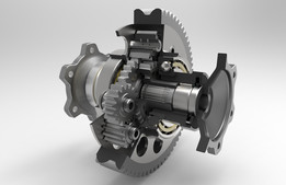
Here is the model of an F1 DIff:
Hi there,
Just like the transmission ratios. I would like to understand why they are there and not just know that they are there.
Regards
Yohann
There are lots of ways to design a differential mechanism. The classic bevel gear differential we all know is one of them.
Besides there are many ways to use a planetary gearset a differential.
To use it on a vehicle axle the only requirement is to have n intermanl ratio of i = -1. You might read through the attached link in my model which is directly from schaefller, it's pretty good.
Hi
I have looked at your page link its essentially a spur gear diffrential. There is some interesting stuff in there, i love the fact that it makes the whole system much more compact and lightweight. However there were very few formulas that i can find. I was thinking would it be the same as a typical planetary gearset formulas or the basic spur gear formulas?
I have looked at your model. Have you done any calculations for yours, if so what calculations?
regards
Yohann
Hey Yohann,
I'm glad that you're so interested in that stuff.
The only formula in that colloquium is the internal ratio of the diff and all it is saying is, that the ratio between the right and the left wheel must be - 1. It is necessary for an equal distribution of Torque from the final drive to the wheels. That's it.
Further you have to make sure the numbers of teeth fulfill the assembly requirement (needed to equally distribute all the planet gears) on the pitch circle.
In my case I of course did these calculations as well as I calculated the gear geometry.
Hi there Alex,
I have looked at your model and i have broken it down to try and figure out what you have done to calculate the gears. I have seen that the planet gears 1 and 2 have 17,13 teeth respectively. The two sun gears have both 33 teeth each.
I have calculated the ratio (-1) this is due to the fact that since both sun gears have the same number of teeth and the rule that the external gearset you take as a negative and the basic formula driven(internal gearset)/drive(external gearset):
33/-33 = -1
However the problem that i am stuck on is that since both the planet gears are meshed together therefor making them have the same module. Each of the planet gears are meshed with their own sun gear therfore the sun gears would also required to have the same module as both the planet gears. However since there is a relationship betweent the pitch circle and the module and both sun gears have the same module and teeth how can one be bigger than the other? I had thought about this for a long time and i thought maybe you could increase the width of the tooth for the larger diameter sun gear so that they could still have the same module however won't that result in two diffrent size teeth therfore they would not mesh at all.
What am i missing out!
regards
Yohann
I can see pack of friction disks there. So it looks like clutch basket. But strange, why is it on output side?
Formula 1 is the King of racing disciplines. Of course they are using limited slip differentials. The clutch is there to lock the differential...
Hi Yohann, I'm glad that you're so interested and motivated to understand things!
You thoughts all are legit so far. The only mistake is, that you talk about an internal gear - there is no internal gear in that type of spur gear differential. The internal ratio just shows, that if you ground (block) the differential input (final drive gear) and turn the left wheel, the right wheel will turn in the opposite direction. Like if you have a mating pair of spur gears and turn one, the other one will turn in the opposite direction. This is what the -1 stands for.
You are also right with the assumption, that all the gears need the same module to make the mating possible. Yeah, the suns have the same module and the same number of teeth but different sizes - That's the genius trick that Schaeffler used! Like you can seen in the colloqium paper they could save axial space since their suns don't have the same size. They realized it by calculating the profile shifts of the suns that way, that the smaller sun can fit under the long planet gear. Which is quite the same as having different tooth width.
I hope I explained it clearly.
Hi Alex,
I have been looking at what you have sent me and i see that i should be looking into profile shifted gears. From what i can gather from this website https://khkgears.net/new/gear_knowledge/gear_technical_reference/calculation_gear_dimensions.html
the profile shifted gears allow the centre distance of the gear to be changed which results in the tooth thickness increasing while the module of the gear remains the same exactly what i need. Also i know that i need a positive shift allowing me to have a wider tooth. However when i comes to the formulas on this website i am a bit stumped. I have been introduced to the profile shift coefficient. Is this a value that i should have pre worked out or is it from a table of some sort. As you know more on this topic than me and i can't find any videos explaining what to do i need your help.
is this the formula x0 = 0.0075*z0 + 0.05??
from this chart.
I understand the concept and i get the formulas however the coefficient and what to do with it has stumped me
regards
Yohann
The Link you sent is very good and contains all the neccessary information to calculate profileshift coefficients. It's pretty tough to do it "manually", mostly a calculation software is used.
No you don't need a profile shift on both gears. But often you use it for both to get better contact and better strength.
Here it is perfectly shown, what profile shifting means to the tooth geometry:
Hi alex
I have managed to compute the profile shift coefficients using help from Matlab and I have created a calculator in Excel to transform the ratios from an example gearbox to all the relevent dimensions needed.
The issue i am having is that as i was making the calculator i was struggling with the formulas not because i could't do the math but there are so many diffrent versions of the formulas used to design spur gears I am not sure which ones to use. Here are the ones used in my calculator can you please check them too see if they are correct or if i am missing any of them.
While calculating the profileshift coefficients from this website:
https://khkgears.net/new/gear_knowledge/gear_technical_reference/calculation_gear_dimensions.html
The website was using these formulas to design the basic Spur Gear:
Then I looked to youtube for help and they had a diffrent set of formulas
Even the online Spur gear calculators are showing diffrent formulas
http://www.me-bac.com/index.php?task=gear_help
I am confused on which ones to use as they are diffrent, could you please help.
regards
Yohann
Hi Yohann,
you're really diligently working on that stuff!
The mistake you did is to look at too many sources which made you confused. Stay at one of them, I'd suggest khkgears was pretty good.
There are many different ways and approaches to calculate gears but they are still similar.
The other mistake is your choice of the formula. This is the way to calculate gear according AGMA. The site of khkgear works with the calculation according DIN. Both may describe the same gear but do this in a different way.
The DIN defines module and profile shifting which very good corresponds with the manufacturing tools and the understanding how gears are cut.
In the AGMA norm no module or profile shifting is defined. Diametral pitch and Addendum/Dedendum are defining the size of the teeth.
You tried to combine DIN and AGMA definition which won't work out well.
BR,
Alex
Hi Alex,
I have now take what you have said and looked into the DIN standard and have come up with a revised set of formulas.
Are these now correct or just ignore trying to make my own set of formulas and just use the ones on KhKgears website.
Ideally, I would like to have my own set because I love to learn and I am determined not to give up, but if it is too much hassle i will just use the others
Do i need to look into creating the involute curve for the spur gear or is that unnecessary.
The pitch radius formula was created from the simultaneous equations that we had discussed about in the other discussion about the transmission.
regards
Yohann
Hi Yohann,
you set of equations look goodso far.
The number of teeth is a real number and doesn't need a formula.
The reference pitch is called reference diameter d, try not to rename the letters for the equations.
Pitch radius/diameter is equivalent to your reference diameter and not needed. If you work with profile shifting then a working pitch diameter appears which is not equal to the reference Ø ==> Center distance gets defined by this value.
Also try to mix up capital letters with small letters, be consistent with all the definitions.
The creation of the involute curve is interesting but not necessary as there is software to create tooth geometry.
BR,
Alex
Hi alex,
Sorry to keep on pestering you and I am very appreciative of your help.
I have made some changes to the formulas and this what I have come up with.
You mentioned that the number of teeth should be a defined value however in my case since I am reverse engineering the formulas and producing the pitch radius, I need a way to find the number of teeth, therefore, I have rearranged the reference diameter formula to work out the number of teeth (z). However, I know that in general practice the number of teeth is a pre-defined value when
using the DIN standard.
I know I have asked a lot from you to help me and i am again very appreciative of this but if the formulas are wrong still would it be possible for you to create a similar table in excel and send me the formulas as a photo. This would ensure that the formulas that I have are correct and I can proceed with the design of the gears in CATIA. I will be creating the gears parametrically since this would maximise my efficiency in modelling the components.
Best Regards
Yohann
Hi Yohann,
so if I understand correctly you're aiming to reverse engineer the gearbox. Since it's impossible to find out all the tooth geometry data I would recommend you to proceed as I told you some days ago:
By assuming an center distance you geometrically define all the reference dimaters as you know the ratios. OK, at least it is more complicated because your gearbox is a standard longitudinal transmission with countershaft. Therefore you have a constant ratio for all gears so the ratios you know consist of two ratios, the constant ratio to the coutershaft and the ratio back to the output shaft. You also need to assume a constant ratio to get results, just play around with an excel sheet.
After this proceedure you will have reference circles and now can assume the numbers of teeth. It's also more or less guessing, you will need to find out plausible values. E.g. for a ratio of i=1,5 of course you won't choose a teeth ratio of 9/6 as it makes no sense. The module will help you since we know that the automotive gears use module in a range of 2-3mm in average.
You don't need to think about profle shifting here as you won't get usable results for reverse engineering. Module, center distance and number of teeth are sufficient to build a CAD-model. This is what I did to design the Getrag gearset.
I hope this helped you.
Best regards,
Alex
Hey Yohann,
how is your work with the gearbox going? I hope to hear some progress ;-)
BR,
Alex
Hi alex,
Yes,the project has officially started. It has been a bit slow however i am making some good progress. I had originally posted the same question on my Grabcad Group "https://grabcad.com/groups/cars-and-automotive-design" and a kind gentleman has provided me with some PDFs on the gearbox design process however since it is in German I have been translating it bit by bit.Even though this is a long process some of the stuff that I am learning is very interesting such as maximum, minimum gear ratio, gear intervals how the rim dimeter, tread profile and other bits of the car all play a part in the design
of the transmission. But as you can imagine I unfortunately don’t speak German therefore making it a drawn-out process, but I am not complaining as this is very interesting and I am loving every minute of it.
Since I was getting a bit frustrated with the gear formulas, I decided I will move on and tackle something else before coming back to them. I would be eternally grateful if I could send me the formulas for the DIN standard gears that you use in your company if possible as I would be able to compare them.
I will be starting to make my Excel calculator soon and parametric model of the gears when I get the formulas correct. Then finally make it in CATIA.
I hope to add this project to my LinkedIn page as a research project so I might consider writing a paper on it to describe my journey throught this project.
Regards
Yohann
Hi Alex,
I have been given theses formulas to calculate the overall powertrain ratio.
And there is an example where I was trying to deconstruct, and I am stuck on how they came to the answer. I have been able to understand all the other equations however the first one (the cubic equation) has stumped me as i dont know how they came to that answer. The question and all the relevant data are posted below. Could you please help me?
Regards
Yohann
Hi Yohann,
in the solution they obvously just filled the equation (1.33) with the values from the exercise and solved it to get the vehicle oveall ratio (i5·ia).
For the first coefficient you just need the maximum power, the efficiency and the reservation factor. Of cource you have to convert the power from bhp into Watt.
In the second coefficient i miss the description of fW. But also here you just have to put in the given values. What I don't know is for which units the equations are designed. The exercise is defined with imperial dimensions which I am not familiar with so I have no idea which convertions are needed to solve the exercise.
Regards,
Alex
Yohann Panthakee,
You have been working so hard to understand the gearbox and I applaud you for it. But I believe you are too close to see the whole picture. The gearbox was designed to match the output of the engine. Each ratio was chosen to keep the engine in a preferred RPM range. To maximize the Horsepower/Torque band. And even that is still only one aspect. I hope that helps you think outside of the box. pun unintended.
Wayne
If you don't receive the email within an hour (and you've checked your Spam folder), email us as confirmation@grabcad.com.