i am studying as an mechanical engineer. i have developed a huge interest in designing field. i drawn several components using tutorials.it was nice experience to in exploring it.but now i need to design steering knuckle for ATV.so please anyone help me on it . if you send me a tutorial it will be very useful for me to learn i will never forget you in my life.i will attach the image of the steering knuckle.the image is just for the shape of the steering knuckle.
Do you have any dimensions, side views, etc.
Designing it accurately from just a photo (a single view) is probably impossible...
Tried to design it, but many dimensions are still missing...
You got this drawing from google, so I searched for more accurate drawings but didn't find anything useful.
If you need it soon, why don't you download one from GrabCAD?
If this is a model that is to teach you how to use the program/draft, then in my opinion, the dimentions given are the important ones. The paper has a grid and a scale for that grid. It looks like you can approximate where edges and features are with respect to the dimentioned features.
I believe there is enough information in that scetch to make this part.
Good luck.
so mike geeser you saying that we can draw using it so you can send me the tutorial
I'll do my best...
I'll probably post it tomorrow
It will also be in its original format, so you can easily know every step.
I have not made any tutorials yet. I dare say it would take some time for me to do so. There seems to be another individual here that has offered to help.
Out of curiocity, what software are you working with? I did not see that in your post, perhaps I missed it.
In solid works I would start with a revolve around the center of the berring so that will be the origin of the part and easy to reference all features from that point.
Then in the front view I would extrude some features to have a solid to work with to revolve cut the tapered holes that are on an angle . Then 8I would extrude cut the profiles in the right view to shape the lugs.
Just take one feature at a time and create a feature then trim it to the specific shape. The whole idea of an exercise like this is to get your mind to think differently. There are many ways to make this part, use the tools you nderstand and chip away at it.
Regards
Mike G.
I'm 99% certain my model is incorrect, but at least it looks a little like the desired result. Having a model in hand would make for an easier experience. Photos of the model would also be a help.
Maybe someone will want to make some changes?
A tutorial for this model could take hours or days to produce. But I'll offer this advice:
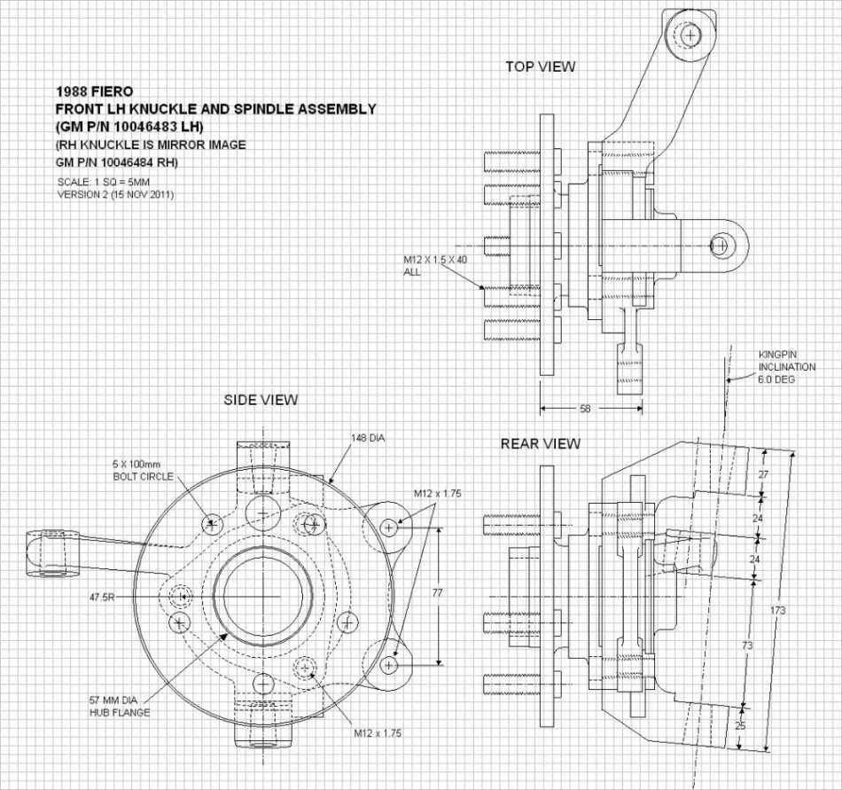
Below is what I came up with.
Problems include, but not limited to:
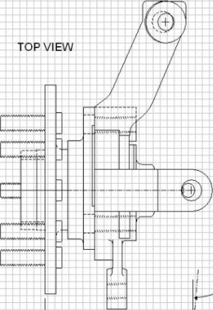
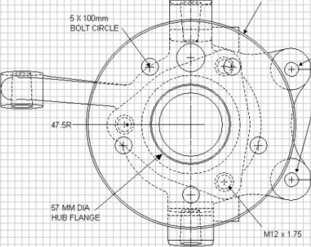
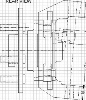
Below is an example of using images to help model the part:
Three reference images already cropped:
Below is the higher resolution image the above clippings are from. Source
Links above say they will be good for two months.
Thanks a bunch, Fred
I've already finished the biggest - most complicated - part and will probably post it later today.
The blocked holes is irritating, but I'm glad you mentioned it (I thought it was my mistake).
Thanks for the pics, advice and models, but I use SW 2016 not 2018, and it doesn't support AutoTrace (Laptop graphics issue).
Autotrace is terrible. Or at least it was the last time I tried it. I'll give it another try and see if anything has changed. It was actually a great add-in when it was provided by Barem-Boym software (~15 years ago), but then SW incorporated the features and it got worse. I've been using Vector magic for any raster to vector conversions.
This model is mostly arcs and circles. The hardest parts are keeping everything from falling apart because of all the tangent arcs (easy to mess up those relationships). The arm that sticks off at an odd angle. And of course, trying to figure out where all the lines are meant to be.
Looking forward to seeing what you come up with.
I'm pretty sure this part is actually two pieces pressed together. I doubt that explains the blocked holes, but it is a possibility.
Look, I'm finishing the model right now...
The delay is because I caught a cold this morning and kept in bed, bad luck.
But the model will still be uploaded today, maybe an hour or two later...
The tutorial is another thing; probably tomorrow.
Sorry for the delay
And FINALLY!!!
This is the model, you can download it and check out the FeatureManager Design Tree till I upload the tutorial of the process (very soon), so keep your eyes open...
Kannan, I've just uploaded an update which is more precise and accurate...
All thanks to Mike Geesser
I've just finished the tutorial, but it doesn't want to update...
The current version contains the first 10 steps, there are still another 10 that don't want to be saved...
I'm still trying to update the tutorial, I'll tell you when it updates.
It will be hard for me to do a video for 2 reasons:
The second one is the important one, as I'm busy right now (and will be busy for a long time).
I'm uploading the tutorial's steps one by one right now, so be ready for the whole tutorial very soon.
Done...
This is the model,
This is the tutorial. (complete)
Hope you like it
Don't forget to leave your opinion
I'll make a video tutorial too, but not so soon.
wow.. I love the way how you present the drawing. how to make this effect? I'm solidwork 2014 user might too outdated..
cheers!
You can make an image just like the one above.
On each reference plane, start a new sketch, then use the Insert - Sketch Tools - Sketch Picture tool. Once done, you'll be able to see those images, along with any model you create.
If you watch some Youtube videos on how to design a car, or other complex geometry, they will perform the same type of setup with the front, top, and side views of the vehicle.
If you don't receive the email within an hour (and you've checked your Spam folder), email us as confirmation@grabcad.com.