

Basic stress analysis by Autodesk Inventor


I recently studied about stress analysis by Autodesk Inventor and I want to share my experience.
This workshop will show you how to check stress, displacement (deformation) of simple beam (3 type)
If you have any suggestion, please feel free to contact me.
-
Step 1: Introduction and prepare sample
Stress
(reference : Stress-Strain Curve | How to Read the Graph? (fractory.com))
Stress is defined as the ratio of the applied force to the cross-sectional area of the material it is applied to.
The formula for calculating material stress:
σ = F/A, where F is force (N), A is area (m2), σ is stress (N/m2 or Pa)
Strain
Strain is defined as the ratio of the change in dimension to the initial dimension of the metal. It does not have a unit.
The formula for calculating strain is:
ε=(l-l0)/l0, where l0 is starting or initial length (mm), l is stretched length (mm)
Stress and strain
Whenever a load acts on a body, it produces stress as well as strain in the material.
Strain causes stress. When applying force that leads to deformation, a material tries to retain its body structure by setting up internal stresses.
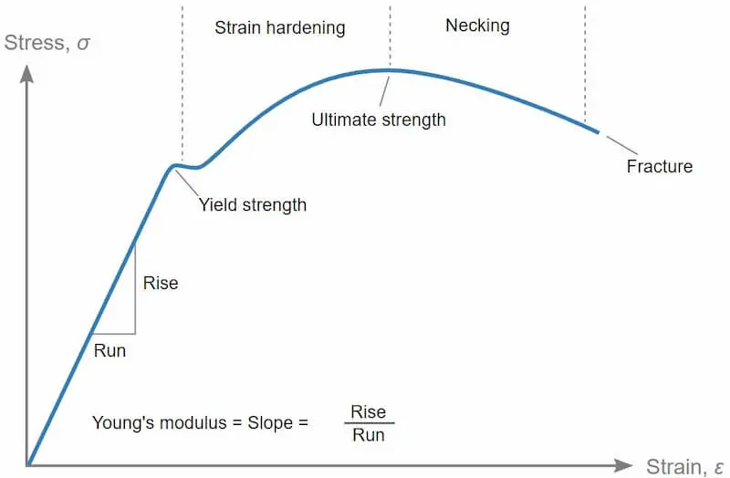
The stress-strain curve is a graph that shows the change in stress as strain increases. It is a widely used reference graph for metals in material science and manufacturing.
In this tutorial, we will make the beam sample as following specification
Beam no. 1 ) Size 200 mm. x 30 mm. thickness 2 mm.
Material is stainless steel SUS304

Beam no. 2 ) Size 200 mm. x 30 mm. thickness 2 mm. with center reinforcement (rib) 4 mm. x 5 mm. Material is stainless steel SUS304

Beam no. 3 ) Size 200 mm. x 30 mm. thickness 2 mm. with Left-Right reinforcement (rib) 2 mm. x 5 mm. Material is stainless steel SUS304

-
Step 2: Go to stress analysis function
At the menu bar, click at Environments tab (1) and Stress Analysis (2)

In this tutorial, we assume that the force that apply to beam is static load
After click stress analysis, the program will show "Edit Study Properties" window
Then select Static Analysis (3) for basic analysis

After click Apply, the model box at left side will show "study" and there are tree diagram menu for analyze stress as follows,
Material, Constraints, Loads, Contacts, Mesh and Results

- Assign material type, the material in this workshop is Stainless steel

- Constraints : Select Fixed function and apply to face as below picture. Removes all degrees of freedom and prevents the face from moving or deforming.

- Loads : Apply force 9.8 N for simulation at the end of beam (edge)

- Click simulate and run to check strength of beam

-
Step 3: Analysis stress data
After program simulation completed, it will show stress data (MPa) as follows,
Remark: Tensile strength, Yield of SUS304 is 215 MPa
In this workshop, max stress is 98.3 MPa. It is not over yield strength.

Next is about displacement or deformation, max displacement is 6.642 mm.

In this workshop, we will simulate all of beam (3 type) and check that which beams are strong by check displacement after apply load. Beam no.2 is the strongest.
The result show as follows,

