

Designing Axial Static O-ring Grooves to "Industry Standards"


This Covers 2/3 of everything I know about designing O-ring seals. I frequently used these while designing production tools. Most the design is based on the standards that are put forth by SAE. Personally, I be going over the reiteration by Parker since it's what I learned. Other references include the Apple Rubble Product and Trelleborg for their proprietary O-ring Gland Calculators, and the help they gave me in building my own. Links to their websites are found in Section 5. All design in this lesson is for "Static Axial Design under normal conditions”.
Disclaimer: while I have completed a BS in Mechanical Engineering and have passed the FE, I am not a PE. While these calculations are standard, published, and I personally have used these practices to design multiple high-pressure tools, I cannot guarantee that they a perfect. If you are in doubt, in a hazardous environment, or using in an application that could cause harm to life, I would suggest double checking with other sources (engineering) and/or extensive testing. Also, my experience is in Oil and gas, in the continental USA. You may notice my practices being bias to API standards and in English Units, I suggest you take all I say with a grain of salt.
Lesson Plan:
Step 1: Background and Definitions
Step 2: Finding a Published O-ring Gland and incorporating it into a design.
Step 3: Designing Custom Groove using the Standards
Step 4: Other Design Recommendations and Drafting Example
Step 5: References and Useful links
A copy of the files can be found at:
How to Design an O-ring Gland to "Industry Standards", Parts and Photos
-
Step 1: Background and Definitions
Why do we use O-rings? Well firstly, O-rings are cheap, standard (mostly) and easily found (mostly). They're not as easy as going to a hardware store but they are found for wholesale prices on sites such as McMaster Carr, Grainger, Apple Rubber along with the main providers like Parker. They can cost as little a few cents, and are pretty versatile.
Side Note: in my experience, most hardware/Auto stores label them with their own number(s) system, so a No. 21 O-ring is actually Size 213, leading to my personal confusion),
Sizing Format: The sizing format is generally a 3-digit number. The first number designates the Series. Each Series has their own cross-section diameter. The second two numbers denote the actual size.
Side Note: They don't line up series to series, (aka 125 O-ring will not have the same ID as a 225 O-ring).
The primary series are charted below:

Durometer: is a measurement of how stiff/hard the rubber is. It can either be "Shore A" or "Shore D", with "Shore A" being more common. It will generally be called out when looking at the material properties. A value of 60 (super soft and gummy) to 90 (almost plastic stiff on smaller O-rings) can be common. The softer O-rings may make a better seal, were the tougher O-rings will have better wear resistance while letting minute amounts of fluid by.
Person practice: of everyday use I use 70-80 Duro, For hazardous situations I use 90A
Note that Duro is generally called out in increments of 5 or ten and will have a tolerance of ±5 (aka a 70A Duro O-ring is 65-75 Duro, Shore A).
Back Ups: While looking for materials you may come upon "Back Ups". I don't plan to go into depth on them since they require separate design. Even if they are rubber, it should be known that they are not used to seal. They keep the O-ring from extruding out of the gland for various reasons like temperature, pressure or movement. They are generally made of stiffer materials either hard rubber, PEEK (plastic), Glass Filled Teflon, Springs, or even Metal. If requested I may write up about what I know on designing these as well.
Materials: There are several materials used for various reasons. Some may be known to you such as silicon, some might be totally new like Alfas, and some might be materials you didn't know you knew. Communally Called “Buna”, NBR is a supper common everyday use rubber. There are lots of selection charts to look at online to help with selection.
Side Note: Personally, I use Buna for standard use, Hydrogenated Buna (HNBR) for Higher Temps (over 225 degrees F) and Viton for extreme Temps (requires backup system).

Parker O-ring Hand Book, Page 2-9
-
Step 2: Simple Gland Look Up:
The simplest thing when adding an O-ring into a design would be to look up a standard gland. There are charts where by selecting an O-ring you can find know glands that are used every day. An example of standard O-ring glands that has been published in SAE AS5857. This table, originally created as an Aerospace Standard, is frequently referenced in other industries. An Example of this table is on Pages 4-5 to 4-8 on the Parker O-ring Handbook.
Pros: standardization. If you make all your parts seal with the same Diameters, parts may be interchangeable, and the Number of different parts or test fixtures you need to keep on hand may be decreased. Another upside is the availability of off-the-shelf back-ups and other accessories that are made to fit the standards.
Cons: It imposes a design limitation. While the differences in one groove to the next size can be very close, there are diameters that can’t be accommodated. Case in point, if you wanted to build a 4.500 in Diameter rod and required a 200 series O-ring, the closest numbers published are 4.487 and 4.615. These glands my not fit within other design parameters and a custom O-ring Gland may be required.
Example 1: O-ring Seal on Water tight 2.5 in Pill Box
For this example, a quick Pill Box was built around a 2.50-12 UN Thread. To make it watertight, an O-ring will be inserted into the cap. Since this use will not be holding pressure, and space is limited, a soft small o-ring will be chosen.

Pill Box Before O-ring design
The thread relief of the pin thread is approximately 2.375 inches. So, we’ll be looking for a 100 series O-ring groove to match that dimension. When looking at standard dimension for a female gland, a #142 O-ring has a rod OD of 2.373.
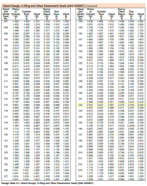
This is close enough to build our design around. The mating gland has an ID of 2.540 and a standard width of 0.140.

Again, we’ll choose a soft O-ring for this, maybe a 70 Duro. (Available at McMasterCarr) or other retailers.

-
Step 3: Designing a Custom Gland using Standards
While it is straightforward to design a standard O-ring groove with a custom diameter, there are a few things that you need to be kept in mind, and some quick calculations that need to be checked.
The basics: While it might seem backwards, if you want an internal groove (also referred as a female gland) the design is based on the Max OD of the rod that passes thru the part. On the flip side an External Groove, (aka a male gland) the design will be based on the minimum bore diameter that the o-ring will seal against. This is the first number that is needed. The second number that is required is the O-ring Series that you want to use. This will drive the rest of the design. The rest is plug and play and easy programmed into an excel file or similar program.
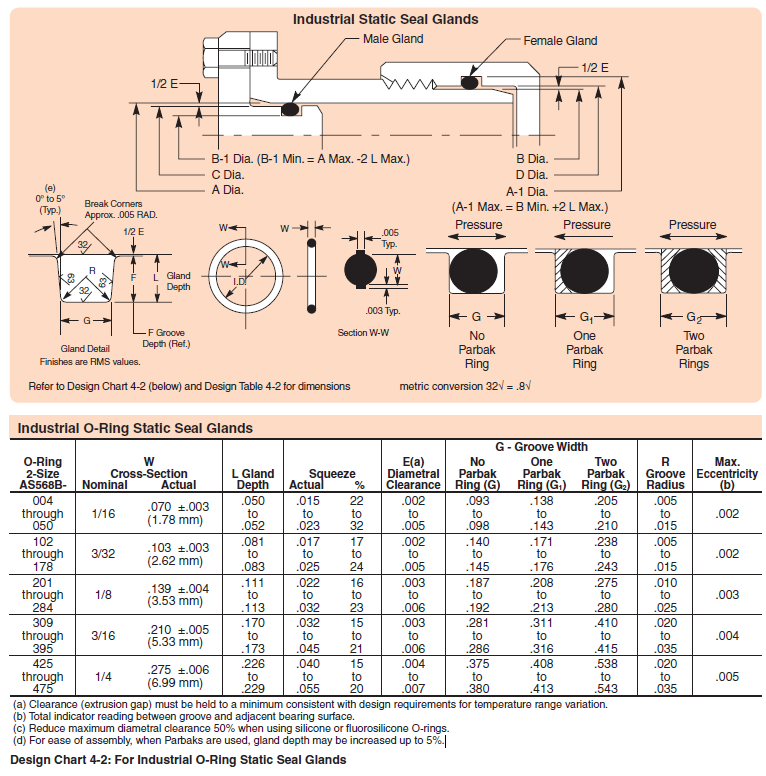
Parker's recommendation (page 4-9 of the hand book)
My Two Cents: in my field, I found that the tolerancing of these parts are a bit high. You can see that it's recommended to call out a 32 finish (.08 Ra) and some tolerances are held to .002 inches. Day to day, I usually call out a 63 (1.6 Ra) Finish and a flat 0.003 or 0.005-inch tolerances with no issues.
In the oil field, these generalizations are called the "fit" (This does not line up with the standard fits given in the Machinist handbook), they are just two general sets of tolerances used (3-3-3 or 5-5-5). By Oil "standards", these are the two options for a "tight" or "loose" fit.
You can call out a custom fit like 3-6-2 where the first number is driving Surface’s Tolerance, the second the diametric clearance (E in the chart above) and the final number is the tolerance of the groove, I would suggest these three never total more than 15 and they need to be tested to ISO standards.
Choosing and O-ring to Fit the Groove: While this is generally as easy as picking the closest O-ring, There are a few things to keep in mind and check.
· Stretch/Squeeze: The O-ring should deform slightly to fit the groove. In the case of a External O-ring, to should stretch over the rod, and in internal groove should be squeezed into the groove. This will make sure the O-ring keeps contact with the seal surface. Trelleborg Sealing Solutions recommends a squeeze of 2-8% (Must be at least 0.5% and do not exceed 9%).
· Fill: The O-ring (and backups) shouldn't completely fill the gland. This is so that the O-ring can deform and not get nicked during assembly. A Max fill of 85% is given. This is usually mitigated by using the standard Gland Depth and lengths given in the chart above.
· O-ring Compression: Again, there should be some compression to guarantee a good seal, but no so must that the O-ring cuts rather than deforming. TSS Again gives the Recommendation of 10-35% for a static seal (6-27% for dynamic)
Simplified Equations: These are simplified equations for the checks above. To make the outcomes more accurate, you can include things such as tolerancing to find the max and minimum amounts; X-section increase/reduction do to O-ring crush/stretch; True Revolve volumes to calculate the fill; etc. These will get you a good ballpark "Yes" or "No" answer.
Stretch/Squeeze:
Stretch % = {(Groove OD)-(O-ring ID)}/(Groove OD)
Squeeze % = {(Groove ID)-(O-ring OD)}/(Groove ID)
Fill (by Area):
Fill % (by Area) = 1.00 - {(Gland Area)-(O-ring Area)}/(Gland Area)
= {(Gland Depth ("L") * Gland Width ("G"))-(O-ring Width ("w")^2 * ...
pi()/4)}/{(Gland Depth ("L") * Gland Width ("G"))}
O-Ring Compression:
% Compressed = {(O-ring Width-Groove Height)}/(O-ring Width)
Example 2: Male Gland/External O-ring
A Rod with an O-ring groove is sealing in a minimum bore of 2.355 and a 200 series O-ring is required with no backups. Use a 3-3-3 fit.
Minimum Bore (A): 2.355
Gland Max OD (B-1) = A(min) – 2*L (min) = 2.355 – 2 * (.111)
= 2.131 inches (+.003/-.000)
Rod Max OD (C.) = A (min) – E (Nominal) = 2.355 – .003
= 2.352 inches (+.000/-.003)
Gland Minimum Width (G) = .187 inches (+.005/-.000)
Nearest O-ring: Size #227: ID=2.109, Width= .139, OD (ref) = 2.387
Stretch = (2.131- 2.109)/(2.131) = 1.1%
Okay, could be a bit loose
Fill =1- {(.112)*(.187)-(.139^2*pi()/4)}/(.112)*(.187)= 72.5%
Good
O-Ring Compression: (.139-.112)/.139= 19.4%
Good
To get a tighter grip on the Rod, the next size O-ring might be wanted:
One smaller O-ring: Size #226: ID=1.984, Width= .139, OD (ref) = 2.262
Stretch = (2.131- 1.984) / (2.131) = 7.51%
Okay, Could be getting a bit tight
Fill =1- {(.112) * (.187)-(.139^2*pi()/4)}/(.112)*(.187)= 72.5%.
Good
O-Ring Compression: (.139-.112)/.139= 19.4%
Good
In my Opinion, since both are within the bounds, would chose the larger of the two bases on the fits when modeled. Though if it was a high-pressure situation I would do more thorough calculations to find the true internal pressure of the rubber:

Left Groove has a Size #227 O-ring installed, Right Groove has a Size # 226
-
Step 4: Other Design Recommendations and Drafting Example
Lead in Angle: To give your O-ring a better chance at "smooshing" into the groove, a lead in angle or chamfer is used on the mating surface. Looking back to the gland designed in Example 2 incorporated into a more complex part:

We can see that since the O-ring stands proud of the surface, if we have a sharp edge, it may cut the top of the O-ring rather than pushing it into place:

Instead we should add a chamfer to push the O-ring down. Insure that the start is higher than the top of the O-ring (.060 inches is common) and at a low angle (20° is preferred, 30° is acceptable). It's also advised to round the edges:

Landing Lengths: The surfaces on either side of the O-ring Groove are sometimes referred to as the "Landing". In this case, there are two O-rings so there is a "center landing" as well. It is common practice that the length of these surfaces are equal to the gland length (.187 for this groove). In cases of length optimization, they should be at least the width of the O-ring (.139). Notice the "landing Length" doesn't include the chamfer on the left end on the male insert.

Double O-rings: in this example I've used a double O-ring. This is NOT two O-rings in one groove, this is two separate grooves. I use them in high stress situations (over 225°F, longer than 12 months in hole, corrosive environments etc.). The whole thought is if one fails, you have a spare to catch. I've also been told many times, "failures are expensive, and O-rings are cheap". These are not needed day to day. I did want to point out that without at least a spacer/backup, two O-rings will feed out or fail together just a bad/quickly as one if the gland is compromised.
Example of a Print for machining:


Excel Program: I highly suggest programing a O-ring Calculator if this is something that you find useful and are doing day to day. I do have my person version, but due to not being vetted I am not longer sharing it. If you are only doing these calculation occasionally, you can get by using Apple Rubbers Program or Trelleborg's App, both of which are free to use.


-
Step 5: References and Useful links
Parker O-ring Handbook:
https://www.parker.com/Literature/O-Ring%20Division%20Literature/ORD%205700.pdf
Apple Rubber Online Gland Calculator:
https://www.applerubber.com/oring-gland-calculator/
Mobile O-ring tool by TrelleBorg:
https://www.tss.trelleborg.com/en/resources/design-support-and-engineering-tools/o-ring-calculator
The Original Tutorial Can be found at:
https://grabcad.com/tutorials/designing-axial-static-o-ring-grooves-to-industry-standards
Files From this Tutorial can be Downloaded at:
https://grabcad.com/library/o-ring-model-and-temp-parts-for-tutorial-1
