

FreeCAD Basic Exercise #3

The objective of this tutorial will be to hang external geometry with the Circle and Polyline tools. Use the Linear Pattern function and use a subtractive function (Pocket) from a face.
-
Step 1: Presentation of the exercise
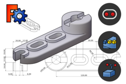
We will model the part illustrated below by the method proposed in the tree structure.

For the dimensions of the part you can refer to the drawing below but they will be repeated in the instructions.

-
Step 2: Modelling procedure
1. Create an oblong volume with the Slot and Pad functions (thickness 12 mm)

2. In a sketch placed above the part, make a projection of the rounded edge to hang a circle which will coincide with the projected arc. Using the Circle function, click first on the centre of the arc and then on one of the peripheral points.

3. Create a 20 mm cylinder from the sketch (using Pad function) and then a 20 mm diameter through hole (New sketch then Circle). Make a groove 12 mm wide and 6 mm deep by applying the Pocket function to the sketch below.

5. Make a Slot through hole according to the sketch below.

6. Use the Linear Pattern function to repeat the slotted hole along the workpiece. Make a repeat pattern 90mm long with three hits.

7. Create a sketch on the face where the slotted holes are located, project two edges with the External Geometry (X) tool and then overlay the projection with the Polyline function. Use the Coincidence function also if a point does not fit.

8. Create a thickness around the hole by creating a new Slot around the first one as shown in the sketch below. Make a 4mm extrusion from the sketch.

9. Create a Linear Pattern with the same parameters as in step 6 (length 90mm, 3 hits). Note that the shape "overflows" from the part.

10. Select the face below the part at the level of the overflowing element and activate the Pocket function. The cavity is created from the face as if it were a sketch. The Refine parameter is used to remove the excess edge.

11. Apply Fillet to the edges of the part for a more realistic look.

