

Helical Gear Shaft Tutorial

Hello, CAD lovers!
Today we're going to learn how to make a Helical Gear Shaft. If you are new to this profile, please leave a like button on this tutorial and follow my profile for more helpful content.
-
Step 1: Create first sketch
First, create sketch of first section following the procedure given below:
(Download the Plan image first and refer to it)

Below is the image of First section Sketch on any vertical plane:

1)First draw a circle of D100.
2)Make a line with length 15mm and give it a symmetrical constraint to horizontal axis(select both end points of line and select horizontal axis at the same time by press-holding ctrl button and open constraint dialog box and apply symmetry)
3)Give Distance constraint to this line and vertical axis of 85mm
4)make a 2 point arc(3 point arc starting with limits) co-inciding the D100 circle and one end point of the line and give 65 Radius to it.
5)Mirror the arc with Horizontal Axis keeping the mirror element.
6)Now, give distance Constraint to both the arcs of 40mm. If the arcs doesn't properly join the line then make sure you have Constraint the arc with the end point of line and not the whole line itself.
7)Select both the arcs and the line and give Rotation with the following properties below:

8)Now trim the inner arcs of the D100 circle.
9)Select the whole sketch and open constraint box and give FIX constraint to it. If it over constraints(Turns Purple) then delete one or two dimensions.
Your First sketch is complete. Exit the workbench.
-
Step 2: Create Further Sketches
Now take an offset plane from the plane you just sketched on, at 45mm.

Now sketch on this plane.
1)select the whole previous sketch and draw 3D Elements of it.
2)Open Scale command and a dialog box like this should appear.

Select the projection, Select middle point and give the value 0.75. Make sure you select Duplicate Mode.
3)Now delete the 3D Element sketch.
4)Select Rotate command at rotate the sketch at 15 degree. Make sure the Duplicate mode is off.

5)Now FIX Constraint the whole sketch and exit the workbench.
6)The same way, Take an offset plane at 95mm from the first plane OR 50mm from the 2nd plane.
7)With the same procedure above, Project First Sketch's 3D Elements, use scale command and Make a duplicate sketch at 0.5 Value. Delete the Projection Sketch.
8)With the same procedure above, Rotate the sketch at 30 Degree and FIX Constraint the sketch.
9) Before fixing, Make sure both the Scaled and Rotated sketches properly joint. The curves may not properly rotate and leave open loops.
Exit the Workbench and check for any Black Dots(Open sketch or overlapping lines)
-
Step 3: Multi-Section Solid
Now open the Multi-Section Solid command from Sketch based features.

*A dialog box will appear. Select the Coupling column. Now click on the ... above it to select the sketches.
*Select all the 3 sketches from first sketch to the last sketch in ascending or descending order. (1-2-3 or 3-2-1)
*In the sections coupling box select Ratio for best result.
*If the preview shows error then make sure the closing points are aligned properly and the directions are also the same.
*If not then right click on the odd closing point, select replace and click on the point you want as closing point. Do the same with the direction.

-
Step 4: Multipad
*Now select the surface of the bottom of the Helical gear(first sketch plane will also work) and sketch on it.
*Draw the following sketch from the below image:

After that, Exit the workbench and select the Multipad tool. It is in the Pad section.

Give the following dimensions starting from the innermost circle to the outermost circle, select each circle and give the length.
-
Step 5: Groove
*Now select the perpendicular plane from the solid and their faces.
*Draw the following sketch with using 2 point arc being tangent to both the lines.

*Now exit the workbench and select Groove command(Besides Shaft command). Select sketch and select the Axis parallel to the shaft.
-
Step 6: Back gear and Pad
Draw the sketch of Back gear from the Plan Image in the first step.

1)Take a line of 10mm.
2) Use Symmetry constraint method to give the line symmetry to horizontal axis.
3) Give distance constraint of 43mm to the line.
4) Draw circle of D76.
5) Draw 2 horizontal lines joining the circle and both ends of the previous line.
6)Give the rotation to these 3 lines with the following instructions.
*Duplicate mode: ON
*Instances: 12
*select the centre point.
*Degree: 360/13
7)Quick Trim the inner part of the circle and give the sketch FIX Constraint.
Exit the workbench and Pad the sketch at given dimension.
The same way, draw a circle on the surface of the above padded solid using the given dimensions in the Plan Image and Pad this circle too according to the given dimensions.
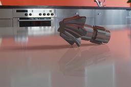
Hence, Your Part is completed!
Additional:
If you want to add material to the part, go to Apply Material command, select the part body and give the desired material to your part.
Usually you won't be able to see the material so go to the View > Render Style > Customize. A dialog box will open. Select the Material box below the Gouraud. If you want to hide the planes then select No Axes box.
Render it to the desired properties using the Render Command if you want to present your part.


Thank you all! Again if you liked my tutorial, Please leave a like and Follow my profile to get regular updates of such Parts and their Tutorials. Learn and Teach!
