

How to model a Control lever shaft using Inventor 2014?

If you are really interested in modeling with Inventor (2014), try to apply every step with respect to their order and watch how you reach the model.
You can watch the live modeling of this part with Inventor 2021 by using this link: https://youtu.be/gOkTy_oJdH0
Enjoy!
-
Step 1:
1. New sketch: a slopped line centered on Center point (length 100, slopped at 7 degrees 21’ from the projected X Axis; two points (P1 and P2) at 29.6 and 51 are added on the slopped line

-
Step 2:
2. Three new work planes: [P1] and [P2] normal to X Axis through points P1 and P2, and [P3] normal to slopped line through Center point; select the line first and the point second

-
Step 3:
3. After taking visibility of [P1] and [P2] and the first sketch, a new sketch on [P3]

-
Step 4:
4. Extrude the new profile between [P1] and [P2] (selected from browser)

-
Step 5:
5. The result of extruding

-
Step 6:
6. New work plane: to create [P4] select successively 1 and 2, in order

-
Step 7:
7. New sketch on [P4]: Circle with Radius=50 at 60 from Center point on the same vertical

-
Step 8:
8. Extrude the circle symmetrically on 31, option Cut

-
Step 9:
9. Fillet Radius 2 on the indicated edges

-
Step 10:
10. New sketch on [P4]: two semicircles at 3 with two tangent lines - superior and inferior - with prescription: the inferior tangent is centered on Center point

-
Step 11:
11. Extrude the closed profile symmetrically on 31-1.88-1.88 (as an expression)

-
Step 12:
12. Fillet Radius 2 on the indicated edges

-
Step 13:
13. New sketch on XZ Plane: the axis (centerline) is coincident with Center point

-
Step 14:
14. Revolve the closed profile using the Intersect option!

-
Step 15:
15. The middle body finished

-
Step 16:
16. Revolve the closed profile in a new sketch created in plan P3: the midpoints on the same vertical with Center point

-
Step 17:
17. The result of revolving with Cut option

-
Step 18:
18. Revolve the ends of part with Join option using two closed profiles in a new sketch

-
Step 19:
19. The result of revolving the two closed profiles

-
Step 20:
20. Fillet four edges with different radii

-
Step 21:
21. Thread the right end using the specification ISO Metric profile / M22x3

-
Step 22:
22. Chamfer five edges with different values

-
Step 23:
23. Hole on the right end of part using concentric option to obtain a countersunk hole at 60° (Ø6)

-
Step 24:
24. Hole on the left end of part using concentric option to obtain a countersunk hole at 60° (Ø3)

-
Step 25:
25. Preparing for creating a sketch in two steps: 1. Click on face, 2. Select „Create Sketch” icon

-
Step 26:
26. The sketch contains a pseudo triangle at 60° with a filleted peak of 0.3 at 13.5 from Center point

-
Step 27:
27. Extrude the „triangle” on a distance of 28, using opton Cut

-
Step 28:
28. Start creating a sketch in two steps: 1. Click on face, 2. Select „Create Sketch” icon

-
Step 29:
29. The sketch contains the projected „triangle” and a centerline (as Axis) at 53 from Center point

-
Step 30:
30. Revolve the „triangle” around the Axis using the option Cut

-
Step 31:
31. Apply Circular Pattern to the last two features around the part axis for 35 times

-
Step 32:
32. Create an work axis using the Axis tool followed by a procedure in 4 steps, starting with right-click on empty graphic space

-
Step 33:
33. Create an work point by clicking successively on a face (1) and the axis (2)

-
Step 34:
34. Create Hole with the option On point by selecting the point and the axis, in this order

-
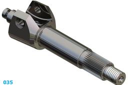
Step 35:
35. Final part

