

How to model a rope drive in Solid Edge?

First run Solid Edge.
-
Step 1:
Then click
"ISO Part" as highlighted with green box in the following figure.
-
Step 2:
Then save it to your working directory.

-
Step 3:
Now check the unchecked box of "Basic Reference Planes".

-
Step 4:
Now from top view tab, change the view to front view as shown in following figure.

-
Step 5:
Before sketching you can also turn off reference planes by unchecking "Basic Reference Planes".

-
Step 6:
From Sketching tab, select line and create lines by endpoints.

-
Step 7:
Click at highlighted green box as shown in the following figure and then select "Dash Dot line" to sketch center line as a reference for rotation.

-
Step 8:
Using left click mark two ends of line.

-
Step 9:
Then right click to finish it.

-
Step 10:
Now use middle mouse button.

-
Step 11:
Using middle mouse button or wheel, click twice to get fit to screen view.

-
Step 12:
Select "Continuous line" to get 2D reference sketch.

-
Step 13:
Using left clicks make sketch.

-
Step 14:
Final shape of sketch must be like this, as shown in following figure.

-
Step 15:
Now click "Smart Dimension"

-
Step 16:
And then from menu you can change dimension standard units.

-
Step 17:
Using same menu you can also change precision of dimension values..

-
Step 18:
Use following dimension values to get the following shape 2D sketch.

-
Step 19:
Now click "Revolve" to get revolved extrusion.

-
Step 20:
Left click on face as shown in figure and then right click outside.

-
Step 21:
Now left click on line to be used as central axis as shown in figure and then right click outside.

-
Step 22:
After selecting central axis enter the degree of rotation as 360, as highlighted with green box in the following figure.

-
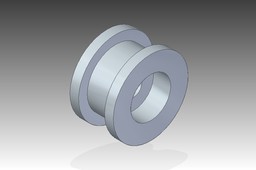
Step 23:
Now select the orientation as highlighted in the following figure and get the Drive Pulley's isometric view..

-
Step 24:
Now click Solid Edge icon of top bar on left side and "Save as Image" to get your 3D model image for rendering of your model.

