

Surface modelling a mouse in Solidworks

When you want to model a mouse in Solidworks, e.g. HP X3000 or similar, there is no easy way to do it. You'll need to create several individual surfaces that are trimmed and filleted into the final shape.
It is not a linear process because many of the input splines are qualified guesswork, that needs to be revised/reshaped to achieve the wanted result. It is more art than engineering...!
-
Step 1: Top Surface, Sketches

Two perpendicular splines are used for a boundary surface.
-
Step 2: Top Surface

Notice that the surface is overbuilt = larger than the actual mouse, so that it can be trimmed to size later.
-
Step 3: Trim Top Surface

The top surface has a flat profile seen from the front, so the top surface is trimmed by a horizontal line on the front plane.
-
Step 4: Front Face, Sketch

A spline on the right plane is used together with the newly cut edge for a boundary surface.
-
Step 5: Front Face

-
Step 6: Side/End face, Sketches

This intricate face goes from convex to concave to convex in order to provide a comfortable grip. The 3 side profile sketches connect to the sweep profile on the top plane.
-
Step 7: Side/End Face

-
Step 8: Trim

Superfluous faces are removed using a Mutual Trim.
-
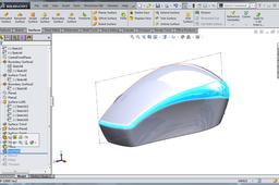
Step 9: Result of Trim

The trimmed surfaces are automatically knitted by the Mutual Trim command.
-
Step 10: Bottom Face

A planar surface on the Top Plane is used to close the bottom.
-
Step 11: Mutual Trim Result

-
Step 12: Fillet, front corner

-
Step 13: Variable Fillet

-
Step 14: Mirroring and Knitting

-
Step 15: Fillet, bottom

-
Step 16: Thicken to Solid

This is the litmus test to verify that the surface is watertight (without holes).
-
Step 17: View from below

-
Step 18: View from side

-
Step 19: Bottom View

The next steps in detailing would be to split the mouse into several solid bodies represinting the buttons, battery cover, etc.
