

Tutorial - Stress Analysis in ALGOR?

Here I am going to show how to apply pressure to a surface. we are going to use the same model.
-
Step 1:
We open the assembly in ALGOR

-
Step 2:
We mesh our model and add constraints (as shown by Sudhir above) and from the setup tab we choose pressure.

-
Step 3:
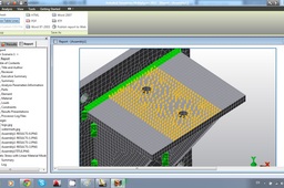
We choose the top surface of our bracket and press Enter. We choose 500N/mm^2 as our input value.
As we can see the pressure is applied to all the surface. In real life conditions this may not be the case. Lets say that we have a beam mounted on our bracket but the beam is not on all the surface.
-
Step 4:
What we should do is "tell" ALGOR where we want the pressure to be applied. So we need to split the surface and we are going to do so in Inventor. (Inventor Fusion can also be used).
Once we open our model we double click on the top part.
-
Step 5:
This opens the modeling mode for this part. we create a sketch on the top face

-
Step 6:
We draw two lines as shown in the image

-
Step 7:
We finish our sketch and choose split

-
Step 8:
We choose the face we want to split and the line in which the split will be made.We click OK.

-
Step 9:
After this our sketch is consumed. Since we need to continue spliting we must go to the model browser,expand the split feature, right click on the sketch and choose share sketch.

-
Step 10:
We repeat step 8 and click return. Our model should look like this. Note that some welds are removed because the face was splited. We should add them manually once more. (see my tutorial about welds here http://grabcad.com/questions/how-to-model-support-bracket-in-inventor-2011 )

-
Step 11:
From the Add-ins tab we choose Start Simulation. this will open Algor.

-
Step 12:
We choose Linear-->Static stress with linear material models

-
Step 13:
We mesh our model again and add constraints as before.
We choose to add pressure, click on the top surface we splited and press enter.
-
Step 14:
As we see only part of the surface is selected. alternately we could select the faces on the edges and leave the midlle stress free.

-
Step 15:
We choose Run simulation and wait for the simulation to end.

-
Step 16:
In the results screen we can choose from a variety of contours to display.

-
Step 17:
We can export a report file. Just go to the Report tab (located next to the model history). You can choose the contents of the report from there and the type of file you want to save your report. PDF, Word, RTF, HTML and Web publishing are available.

