

Up for a challenge

Here is how I did it.
-
Step 1:
Sketch on front plane
A few dimensions
-
Step 2:
Revolve 180 reversed direction.
180 revolution will become very handy later on.
-
Step 3:
Load toolbox
from menu
Toolbox -> Configure
For how to customize thread, refer to this: https://www.youtube.com/watch?v=DKwnvsM8-xIUnder Sizes use numbers in the the last row

-
Step 4:
Under thread data use numbers in the the last row

-
Step 5:
Save and open hole wizard
Choose these settings
-
Step 6:
You should get this.
I tapped the hole so early because there are things with dimensions to the tapped point.
-
Step 7:
Sketch on right plane
All dimensions are from PDF file except Ø0.4670 is measured in CorolDRAW. Refer to my previous comment for reasons.
-
Step 8:
New sketch on right plane
Convert the line and extend it to pass the revolved body
-
Step 9:
Use this one line sketch to extrude cut

-
Step 10:
Sketch on front plane
Tangent relationship is not necessary at top but it can give me a fully defined sketch.
I recommend finish this step before you revolve the upper cylinders. Otherwise this cut intersect with them and you need to create a reference plane and do extrude cut up to surface, which is more work.
The small circle in the middle can be replaced with just a point. It is useful later.
-
Step 11:
Now you can revolve and merge and leave the center hollow.

-
Step 12:
Revolve cut the lower part

-
Step 13:
Sketch on this flat surface and the center of this circle should align with the partial circle in the sketch for revolving. That is why I put dimensions in page 2 into that sketch.

-
Step 14:
Because I revolve 180 degrees, now you can create a reference plane as pictured.

-
Step 15:
Sketch on this new plane
Convert the edge and use R0.343 from page 5
Offset 0.284 from page 3
0.1788056 from page 3 is not used anywhere. 0.27 is hard to tell from what to what.
-
Step 16:
Sketch on top face of upper cylinder
dimensions in page 4
-
Step 17:
Hole wizard as pictured
Position snaps to points in previous sketch
-
Step 18:
Revolve cut 180 use temporary axis

-
Step 19:
Pattern as pictured

-
Step 20:
Now mirror body and merge

-
Step 21:
Use the small circle in the sketch here as reference and tap a hole

-
Step 22:
Tap another hole here snap to the center of the bigger semi circle

-
Step 23:
Chamfer

-
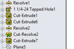
Step 24:
Finished feature tree. I do not think I can make it any shorter at the moment.
I hope this helps.
