

Learn about the GrabCAD Platform
Get to know GrabCAD as an open software platform for Additive Manufacturing
Visit our new homepage


Hi, i want to make a spur gear modul is 2 and number of teeth is 5. But i see only 10 at the number of teeth column in solidworks?
help please

Do you mean the gear(s) in Toolbox? Those are a good starting point, but they do not produce every gear. I'm not positive they have a proper tooth profile either, I think they are meant to look like a gear, they are not meant to be used to manufacture gears.
Files can't be uploaded in Groups yet, so use this url to download a step file of the gear shown below: http://www.filehosting.org/file/details/748098/5%20Teeth.STEP


A gear of module 2 with five teeth is not a proper gear. If we go back to the real engineering world pre 3D CAD modelling, where we had mechanical engineering based on thousands of years of human experience, sound mechanics and the work of many clever people who transferred the real physical world into a set of engineering theory and rules that will actually work. Going back into this pre 3D solid modelling world, I have reached into my bookshelf and the first book I have pulled from the shelf that covers the basics of spur gear design is a volume "Machine Design", my copy is the third edition published by MacGraw-Hill in 1943, written by two professors of mechanical engineering at the University of Wisconsin, P. H. Hyland and J. B. Kommers. This was a period in history way before Solid Works, all our mechanical devices started out as an idea, a requirement, with the first step being the designer, thinking, working out the basic mechanics and understanding the basic principles of how the machine and its basic elements work along with all the parameters needed for these elements to function correctly. Adding wonderful tools like 3D solid modelling software has clouded the clear thinking required for good mechanical design, many have been seduced by the point, click, drag and you can create wonderful pretty things. Unfortunately the software often does not know the difference between a load of garbage and good design, it only produces what it is told to do. In this case with generating a gear in Solid Works it gives us a hint that this is not sound mechanical design by having 10 teeth as the minimum in the default.
Now getting back to basics of gear design. This book starts out, in the chapter on toothed gears, by setting out "The fundamental law of toothed gears states that normal to the common tangent of the tooth profiles must always pass through the instantaneous centre or pitch point, if the pitch cylinders are to roll with a constant velocity ratio '. To get a clear idea of what this all means open up a basic mechanical component design text and read the chapter on gears, or if this is too much effort you may find a youtube video on gears that will fill in the blanks. The whole point of using gears to transmit power is being able to transmit high torque loads at a constant velocity ratio. Vee and flat belt drives can transmit power at a constant velocity ratio but friction limits the amount of torque. Roller chain drives can transmit higher torque but the velocity ratio is not constant. For a gear to fit in with this definition as close as possible it is important that the tooth profile is designed to fit with this definition an involute or cycloidal curve fits this requirement, so this is the common tooth profiles used. Also the gear centre distance must be correct for the rule to apply. As we want all our gears to be standard and interchangeable the teeth profiles are defined by standards. For modern gears we define this tooth by the gear module. If you feel you need to know more detail get a book and find out for yourself.
For all gears to have a correct and proper profile with the teeth able to mesh and transmit power correctly at a constant velocity ratio with all teeth made to standard profiles, we come across the first limiting factor in gear design, the minim number of teeth that will fit in a gear. The physical universe, mathematics, geometry decides this number, below a certain value there is not enough room, the tops and bottoms of teeth in a set of gears interfere and will not fit together properly. This number is more than 5. If we attempt to make a gear of only 5 teeth, in any standard gear module it can't be done. If you try you end up with that undercut non-gear FredSWUG created, as well as being hard to make with standard gear cutting tooling and methods, the relief in the teeth are getting into the circular pitch part of the gear on the line of action for the meshing gears. Sometimes you see these non-gears use it items like the legs of drawing compasses from the old days when engineering drawings were hand drawn. These work in this role because the centre distance is moved out to remove the interference between teeth. Increasing the centre distance increases the effective pressure angle and we use only the tips of the teeth and are not concerned with transmitting large torques.
There are formulas for working out minim teeth to avoid interference or having to undercut teeth to give clearance. If I look this up in my Machinery's Handbook N = 2a x cosec^2 pressure angle this gives us a minim number of teeth of 17 to 18 for a 20 deg. pressure angle a = addendum = 1 and for a 14.5 deg. pressure angle gear 32 teeth. With modifying the tooth shape we can make gears down to about a minim of 10 teeth, what Solid Works tries to tell us, so they must have put some thought into their gear generator. If you wish to learn how the standard involute tooth is modified to achieve this look it up in Machinery's Handbook or any good engineering design text.
I am no expert on gear design, the last time I designed a gear driven machine was in about 1996, big slow moving gears, plenty of room to fit them in, about as simple as designing gears gets, no 3D modelling software used, just a good textbook to follow, calculations done with pencil paper and a calculator, checked by colleague to see I had made no errors, then drawn 2D using ACAD software.
Our flash modern 3D modelling software may produce great looking models but it does not do the real design we do that with a combination of creative thought knowledge, experience education and help from our colleagues. Our software is just a tool, if we tell it something stupid it does not know the difference, we need to learn how to tell it the right information
Less than 17 no. Of teeth count is very common!
one
example of such gear reduction can be seen in manual chain pulley blocks.
5teeth pinion / 18 teeth side gear ,3 mod
4teeth pinion / 19 teeth bull gear, 3 mod
however, these have special profiles by manipulating the Outer Diameters and depth of cuts, while keeping the pressure angle to be 20degrees. 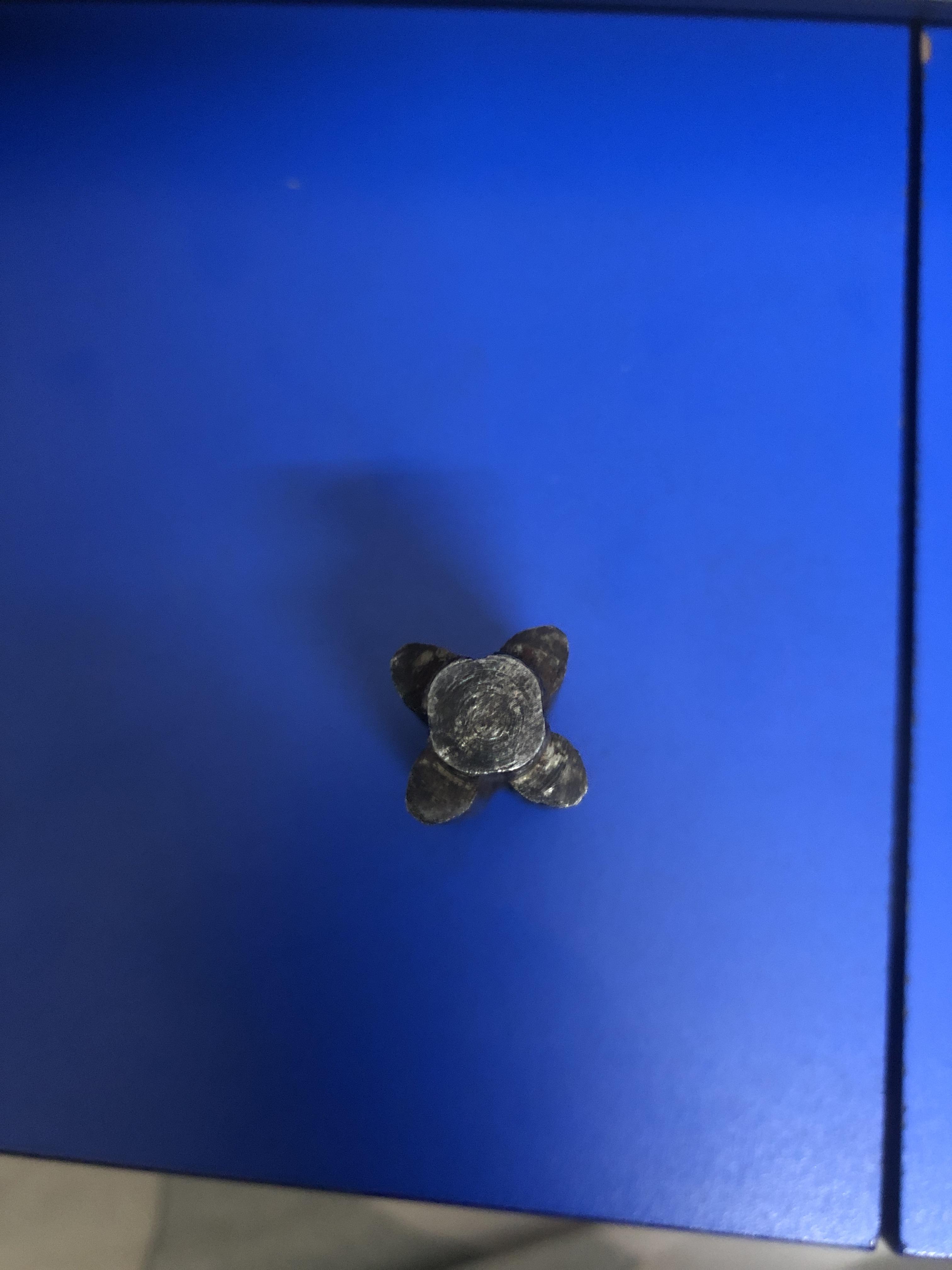
If any one can help designing such profiles then it will be a great help.
specially in 3d modeling softwares.
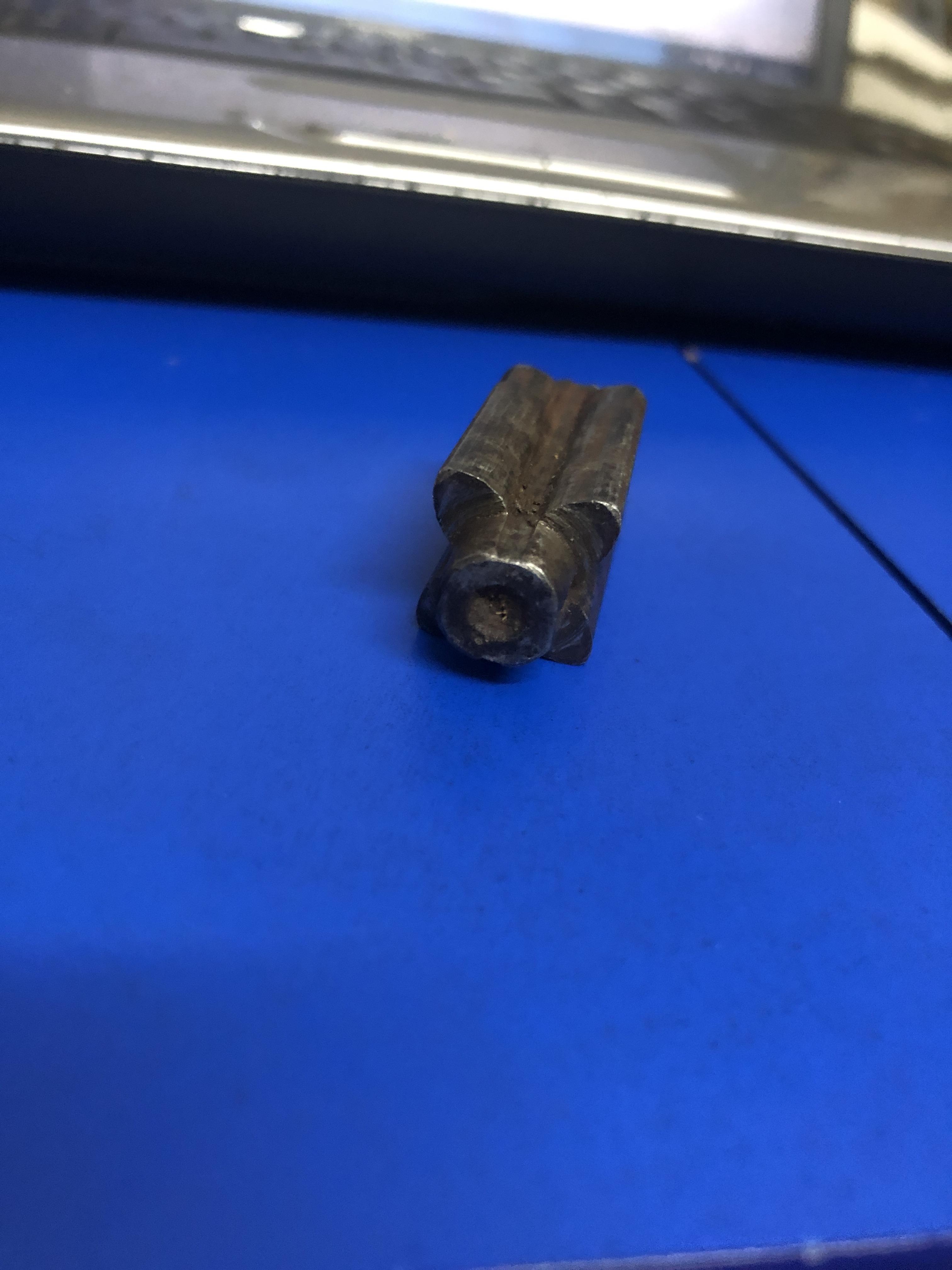
photograph of 4 teeth 3 mod pinion straight from the triple spur gear chain block


If you don't receive the email within an hour (and you've checked your Spam folder), email us as confirmation@grabcad.com.