

How to create model of FUEL CELL in SOLIDWORKS?

how i can create model of Fuel Cell on SOLID WORKS?


Accepted answer

please can u help me how greate solid oxide fuel cell tubular with gambit please reply
5 Other answers

There are dozens of ways to model it, but I would start with sketches that represents the size and shape of the flowfield, the manifolds, and other key aspects of the plate and build the rest of the geometry upon that sketched 'layout'.
Extruded boss/base, extruded cut, and swept cut (or swept boss/base, if modeling the inverse) will be the features used most often.
Plate geometry is relatively simple, feature-wise, the hard part is controlling the geometry such that it's easy to make changes.

Dear Robet Hoyt
This is the only layout of the PEM fuel cell.I want to build 3D model of PEM fuel cell of inside.I mean the all inside design like,


It depends on what you need to do with the model. If it's just a one-off model for a visual reference, you can model a single portion of the flow path (probably works best with the 'sweep' feature) and 'pattern' to hack it together fairly quickly.
However if you need to make multiple iterations, a common 'base' part, or layout for the plate and other component models to to reference, and well thought out equations and sketches that behave will be key to making rapid iterations of fuel cell flowfield and plate designs.
Variables such as 'pitch', 'land width', 'channel width', 'channel count', etc., are important and ultimately drive the flowfield layout.
CAD-wise, getting robust control of the flowfield geometry is 80% of the battle (or more) with fuel cell plate (and associated hardware) development designs.
Dear
How to start creating model of PEM Fuel Cell in SolidWorks?
Here's how I'd go about it:
1. Layout sketches
2. model one cycle of the repeating pattern
3. pattern the bodies
4. clean up features to extend top channels and trim away extra bottom channels.
5. combine all the bodies into a single body.
6. repeat technique for cathode plate, adding a cut at the end to create the variable depths
For a one-off, it's all basic features, there's really nothing tricky about it until you want the valleys and/or lands to be anything other than 1mm, or more parallel paths are added, at which point this model starts to get cumbersome and needs more 'smarts' built into it with global variables, equations and such.
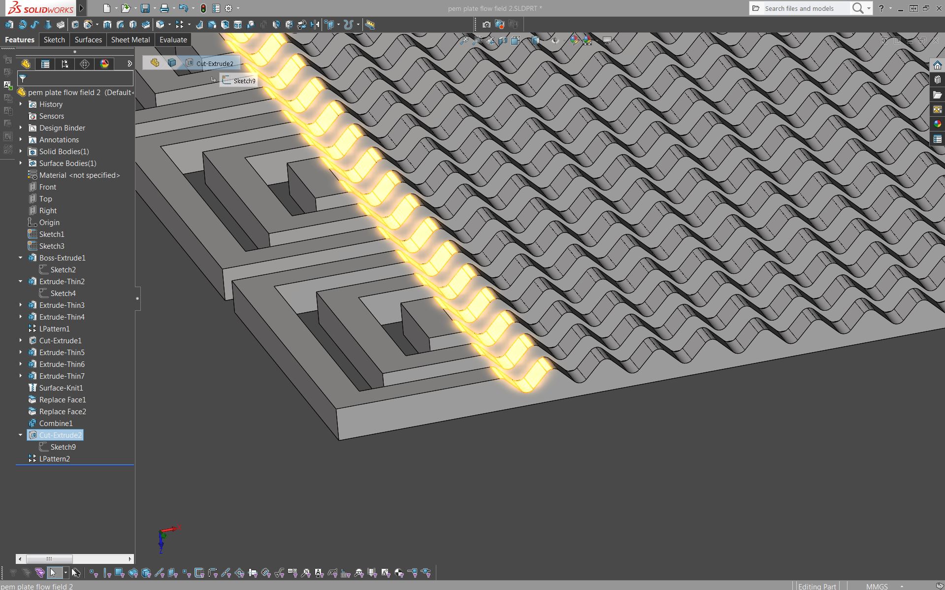 pem plate 2.JPG
 4_clean up and combine.JPG
 3_pattern_flowfield.JPG
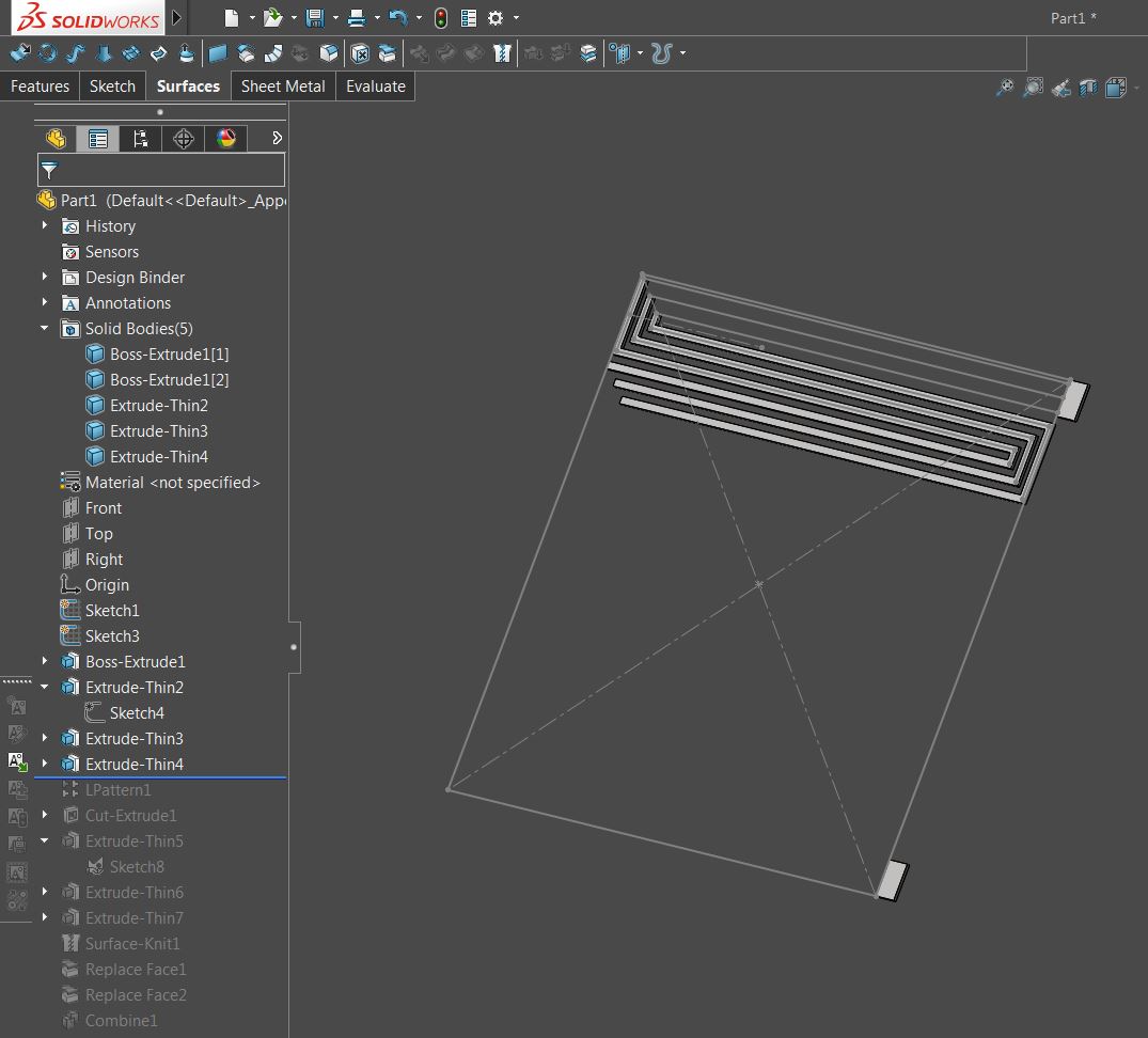 2_one flowfield cycle.JPG
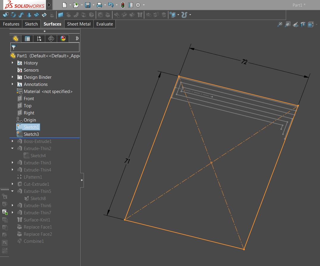 1_layout sketches.JPG
pem plate flow field 2.SLDPRT
pem plate flow field 1.SLDPRT
1_layout sketches.JPG
pem plate flow field 2.SLDPRT
pem plate flow field 1.SLDPRT
