

how to make plastic mould die for this model?

i need plastic mould die for the model attached.. material: LDPE in solidworks
8 Answers
This part is not designed for injection molding.
No drafts on the side walls, no fillets, different wall thicknesses (use shell function), with are necessery for good injection molding parts.
First thing is adapt the design for injection molding.
Tip : if you design a symmetric part in SW : design the half of the part and at the end use the mirror command. Save you a lot of time to design and to make changes afterwards.
The design of the part ask for a complex inection mold.
Depends on how many piece you want but if you want a cheap mold for low quantity you can consider the option to split the part in a left & right part for molding and weld the 2 parts together (mirror welding) for the finally part.
Is LDPE plastic not too soft for this part? Think more on HDPE or PP.
Many success !


To add on with Roberts comment,
Here is a gentlemen on the site that has his own company and many mold designs already posted to his page that you could check out.
Might be a resource to use if in need of some redesign.

As everyone already mentioned, this part is not ready for injection molding.
Side action tooling and sink marks can be lived with, but a lack of fillets, and especially a lack of draft angles will prevent this part from being mass produced.
Divakar,
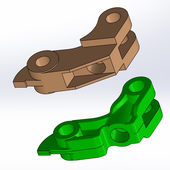
here's a fast example design of a possible injection molding part (green body). I don't know the application of the part so some details need still to adapted. The part is designed with the parting face in the middle, and a wall thickness of 3 mm.
For a optimal part design the best is sitting around the table with the mold designer and the injection molder and discuss in detail the whole part in respect of the assembly where the part is used.
Many success !

This part doesn't appear to be designed with injection molding in mind, it looks more like a machined part.
As designed this part will require side actions in order to eject, unless the thru-holes can be drilled in a secondary process.
It will also have sink marks where the wall thicknesses are excessive, injection molded parts like to have relatively consistent wall thickness, or at least gradual transitions between walls of varying thickness.
Is there a pull direction in mind for this part yet? Because it could go a couple ways as designed and maybe there's a preference or functional requirement that drives the pull direction decision.
My advice is to consult a mold maker about this part to get their advice first before committing to molding this design as-is.
Hopefully there was something lost in translation, because it sounded like. "Please give me some advise. I already disregarded everything you suggested previously".
Anyway, the part is not designed for injection molding. I guess that won't stop anyone from trying, but the part will not release easily from the tooling. It could be a slow manual process to extract each piece. Or if it does eject, you are going to be left with deep ejector marks, and "skid marks" where the part drags along the wall of the tooling.
If this is an exercise for school, then you are doing OK, and it looks like you have the basic idea. If you are doing this for production, then no, you need to modify the base part before making tooling.
A screenshot is attached of two things you might investigate.
There is an odd skin inside the tool which can't be there.
An the sharp 90° intersections on interior corners can't be made in a cost effective manner. Someone would need to EDM those, and then polish the result. It is going to cost time and money to have that sharp feature.
Should the ejectors be tapered? I don't do tooling design, so I'm not sure how they are normally created.
Square 90° degree corners on a plastic part are going to be prone to breaking. Most of the intersections of faces should be blended with fillets.
The part still has massively thick areas which will lead to undesirable sink marks, and possible dimensional issues as the material cools at an uneven rate.
Having side pulls will increase the cost of tooling.
I don't believe this is ready for production. 3D printing as a test, maybe. But not mass production.

friends, finally i made mold on my own, regardless of your answers...
any suggestions on my design??
eagerly waiting
No cooling lines, no vents, no assembly hardware, bushings, ejector mechanism, etc etc etc....
Injection molds don't inject between the core/cavity plates as you have it, the main sprue comes in perpendicular to them.
What kind of mold is it?
