

1. Introduction about CFD Fluent-ANSYS

In this discussion, we will see basic introduction and changing setting for optimal and user friendly use of ANSYS. This all deals about, how to customize systems, display properties, uses maximum core for meshing, changing background color, and lot's more.
-
Step 1: Overall Preview
The overall preview of ANSYS window (workbench) has been shown below.

In this one can find the overall view, also I request you note the locations of links.
One can download free ANSYS student software -> https://www.ansys.com/en-in/academic/free-student-products (Copy and view in new tab) and choose Ansys Student and install them. I use 19.0 but never tried 19.1. It's your wish that you can download all the three.
-
Step 2: Types of Systems.
The total system in ANSYS is- Analysis, component, custom and design exploration.
Analysis system:
In this system you have main systems that are used for analysis of any fields like structural, thermal, fluid, electromagnetic, etc., One can use lot of inter-relation with above systems.

Component System:
In this one find a single component that are found group on Analysis system. It also includes the analysis on pump, turbine, and turbo-machinery analysis.

Custom Systems and Design Exploration:
In this system, a variety of template can be found for easy access with design optimization using advanced method such as six-sigma method for accurate results.

-
Step 3: Customize your Workbench
For customizing go to tools >> options and you can see lot's of options.

Make sure you are in Geometry Import. In that from general option choose your preferred geometry editor as DesignModeler. Make sure you have your own appearance from appearance tab and choose your favorite color.
Also for directory temporary files you can change location from Project management.

-
Step 4: Project Schematic
Usually at starting, this page will be blank. But for analysis to be started you have to insert any one of systems. Note: some systems may be dependent while others don't. You should know the difference.
You can also link the systems so that the results are transfered to other system. Usually multi-physics uses inter linking of systems. One such example is as below.

-
Step 5: CFD-Fluent
From Analysis system, drag and drop Fluid Flow (Fluent) or you may double click on it.

These are brief introduction for the passage to fluent.
- Create geometry using designmodeler or you can import as stp from any software.
- Next create mesh, mesh is the method of breaking model into 'n' number of elements and nodes which then later used as approximation. Greater the node, accurate the solution is and better convergence with increase in time taken for solving.
- Creating Named selections, which means that you have to name the boundary (edge, face, body) for creating boundary condition such as inlet velocity, pressure range etc.,
- Input the boundary condition for domains as required.
- Initialize the case.
- Solve the problem with as much of iteration. Iterations are self-correcting and adjust the vale. Thus greater the iteration greater the accuracy of solution.
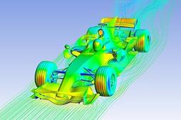
- Post-process the result. That is viewing the plots, contours, vectors etc.,
