

Ansys Static Structural Analysis | Ansys Workbench Static Analysis | Custom Meshing Ansys | CADable | CADable tutorials

Welcome back to CADable. This is Engr. Ibrahim Omer. In this tutorial, we will learn how to simulate a bar with a hole in the center using Ansys Workbench. The objective is to perform a static structural analysis. Let's go through the steps involved in this process.
Step 1: Select Analysis Type
We begin by selecting the analysis type, which in this case is static structural. Ansys Workbench provides various analysis types to suit different engineering problems.
Step 2: Define Engineering Data
Next, we need to define the engineering data for our simulation. We will apply structural steel as the material for the bar. Ansys Workbench offers a material library, but we will also cover how to select a different material if needed.
Step 3: Create Geometry
In this tutorial, we will use Ansys Design Modeler to create the geometry of the bar. However, you can also import geometry from other CAD software such as Solidworks, Catia, or Fusion 360 into Ansys Workbench.
Step 4: Meshing
After creating the geometry, we move on to meshing or discretizing the model. We will use a default mesh size of 0.5 inches. Additionally, we will cover how to create a custom mesh if desired.
Step 5: Apply Boundary Conditions
Now it's time to apply the boundary conditions. We will fix one face of the bar to represent a fixed support and apply a load of 200lbf in the positive x-direction on the opposing face. The boundary conditions define the constraints and loads on the structure.
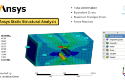
Step 6: Solve and Evaluate Results
Once the boundary conditions are applied, we solve the problem to obtain the deformation, equivalent stress, maximum principal strain, and reaction forces. We will also evaluate the results, such as animating the deformation and examining the stress, strain, and reaction forces. Ansys multiplies the deformation by a certain factor for visualization purposes, but we will view the 1:1 deformation.
Step 7: Analyze Results
During the analysis, we will observe that the force in the x-direction matches the applied force. We might encounter small forces in the y and z-directions, but these can be disregarded as numerical errors. We will also examine the maximum and minimum stress values and use the probe command to determine stresses at various locations in the structure.
-
Step 1:
