

AutoDesk Inventor Laser Cutting Tutorial - PVCC

This is a simple tutorial to laser cut parts using Inventor. This method circumnavigates the need for Illustrator by enabling the user to 'print' their cut directly from a pdf viewer that enables vector graphics such as Adobe Acrobat. The tutorial was put together for use by Piedmont Virginia Community College (PVCC) students and staff but should work similarly with other setups.
-
Step 1: Create a Drawing
The first step after designing your part is to create a drawing file. Do this by clicking 'File' then 'New' followed by selecting the 'Drawing' option.

-
Step 2: Delete the Border and Title Block
Next the border and title block need to be deleted so they aren't engraved when you go to cut your part. Control clicking will allow you to select both features then right click and select 'delete'.

-
Step 3: Set the Laser Cutter Dimensions
Right click on your sheet and select the 'Edit Sheet' option to bring up the menu to change the size of your cutting surface.

-
Step 4: Setting the Size
Under the 'Size' drop down menu you should choose the option 'Custom Size (Inches)'. Set the height to 12 inches and the width to 24 inches for the laser cutter currently used by Piedmont VA Community College. Setting the size to match the cutting surface will avoid any scaling issues that you may run into otherwise.

-
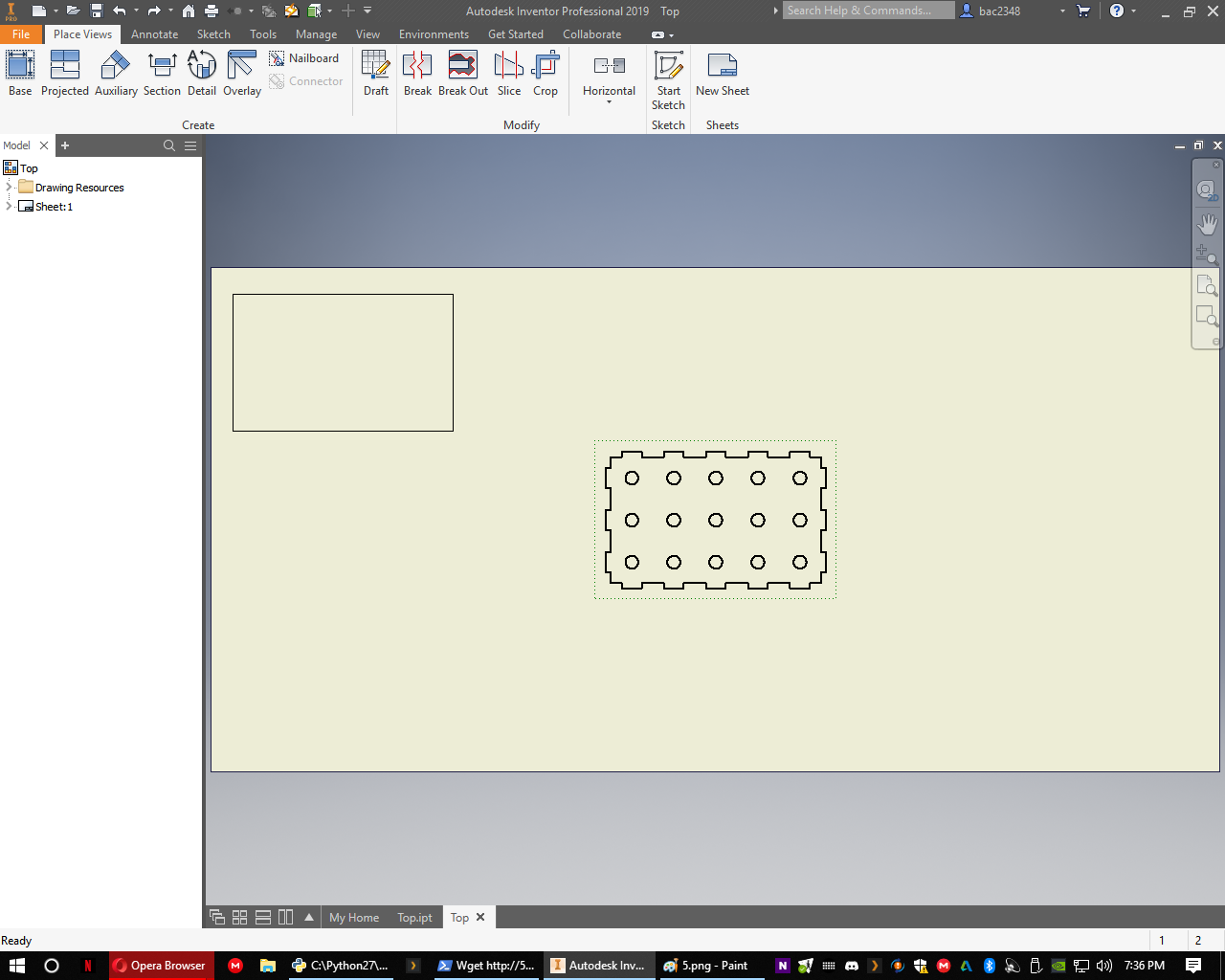
Step 5: Place Your Drawing View
To place your first view on the drawing select the 'Base' option in the upper left corner. Inventor will automatically set the file path to the most recently edited part, however, you may change this by selecting the magnifying glass and navigating to your part file. Next you may need to adjust which face of the part is face up by using the view cube. Double check that your scale is set to '1:1' otherwise your part will not be cut out with the dimensions you used to draw it. When all that is set hit 'OK'.

-
Step 6: Move Your Drawing
To move your drawing click and drag the dashed line around the base view. Place this approximately where you want it to cut out on the laser bed. Note that so long as the whole cutting surface isn't being used minor adjustment to the position may be easily made in the UCP laser cutting software. If you need to cut multiple parts out at once repeat the previous step and continue to adjust the view placement until satisfied there are no overlaps.
-
Step 7: Open Styles Editor
Next select the 'Manage' heading to switch to the manage ribbon. This will allow you to apply different values in bulk to a verity of settings. Click on the 'Styles Editor' to bring up the next menu.

-
Step 8: Change the Visible Layer Properties
Click the '+' beside the 'Layers' option on the left pane and select the 'Visible (ANSI)' option. The right pane should populate as shown. Select the black box and change the color to pure red and the line weight to 0.001 in. Hit 'Save and Close' in order to apply your settings to the current drawing file.

-
Step 9: Check Your Work
All of your lines should be thin and red now that the settings have been applied. Check over everything to ensure this is exactly how you want the laser to cut before moving on to the last step.

-
Step 10: Export Your PDF
Select 'File' then navigate to the 'Export' option. Choose to export as a PDF and tell Inventor where you want to save the PDF it creates. Once you have your PDF on the laser cutter computer open it in Adobe Acrobat and print it out as you would any other document to the laser cutter. Acrobat shouldn't try to scale the drawing at all but it is good practice to double check before cutting.

