

Bench power supply enclosure (PartDesign, SheetMetal "Fold a Wall" function, TechDraw & Inkscape)

This tutorial explain how to make a sheet metal enclosure on FreeCAD 0.19 using a Bench Power Supply as an example. Step 1 to 5 show how to model the enclosure starting with flatten sheet metal. Step 7 to 8 provide some tips to make drawing with all required information to manufacture the enclosure.
-
Step 1: Modelling of the sheet metal shape
1.1) Go to Part Desing WB ;

1.2) Creates a new sketch on XY Plane ;

1.3) Sketch the geometry as below ;

1.4) Constrain geometry as below ;

1.5) Leave the Sketch editing mode ;

1.6) Extrude a solid of 1.5 mm from sketch (with Pad function) ;

1.7) Make a symetrical extrusion with Mirrored function in the plane corresponding to the vertical sketch axis (here YZ) ;

1.8) Set Refine parameter to "true" to remove the centre edge.

-
Step 2: Sketch of components mounting holes
2.1) Create a new sketch on face to be drilled ;

2.2) Sketch vertical construction lines at the bends to add visual cues to the sketch;
2.3) Sketch circles as below, positioning them approximately at their final location. There are 5 circles in the first section, 7 in the second and 1 in the third ;

2.4) Apply vertical and horizontal alignment constraints as below, by selecting the centres of the circles to be aligned and then using the Vertical and Horizontal functions (shortcuts "V" and "H");

2.5) Add diameter constraints as follows: 12.00 mm, 11.12 mm, 6.30 mm (2 slots), 9.52 mm (2 slots), 3.17 mm (7 slots) ;

2.6) Add the distance constraints starting with vertical constraints as follows;

2.7) Add horizontal distance constraints as follows ;

2.8) Finally, add a symmetry constraint.

-
Step 3: Sketch of ventilation holes
3.1) In same sketch, add a circle of diameter 6.35 mm with distance constraints as below (76 mm and 13 mm);

3.2) Select the circle and click on Rectangular Array function;

3.3) Set rectangular array with 4 columns and 3 rows, equal vertical/horizontal spacing and constrain of separation between elements ;

3.4) Click on OK and then in any direction to place the array ;

3.5) Constrain the elements with a spacing of 13 mm and a horizontal direction;

3.6) Make a Symmetry of the rectangular array ;

3.7) Constrain the symmetry with a horizontal alignment and a distance of 25 mm.

-
Step 4: Creates the holes from sketch
4.1) Use Pocket function to create holes from the sketch ;

-
Step 5: Create bending edges
5.1) Create a new sketch on sheet metal face ;

5.2) Create a Line at the first bend with Coincidence constraint as below ;

5.3) Leave the sketch editing mode ;

5.4) Repeat the same operation for the second bend : create a new sketch -> create a line -> leave the sketch ;

5.5) Same for third bend ;

5.6) And so on...

-
Step 6: Fold the enclosure
6.1) Go to Sheet Metal WB ;

6.2) Select the designed part and first edge ;

6.3) Apply Fold a Wall function to fold a wall at a chosen line ;

NB : invertbend parameter allow to fold in other direction, so that the right side is folded ;

6.4) Repeat the same operation for the second fold : select face -> select edge -> Fold a Wall ;

6.5) Same for third fold ;

6.6) And so on... Enclosure is now complete !

-
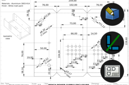
Step 7: Place view and quotations
7.1) Go to TechDraw WB ;

7.2) Add a new page using a selected template or using the default template ;

7.3) Add a 2D projection view of unfold sheet metal ;

7.4) Add a horizontal length dimension, vertacal lenght dimmension and diameters as below ;

NB : Each diameter is placed on only one circle so as not to overload the drawing ;
7.5) Save the current page as SVG file.

-
Step 8: Place lines and annotations
8.1) Open the drawing with Inkscape software ;

8.2) Use the Bézier curve and line segments function to place all the lines, starting by folding lines represented by interrupted line ;

8.3) Placing mixed one-point lines for axes of revolution and symmetry ;

8.4) Placing text for annotation and product information to finish the drawing ;

8.5) Remaining space can be fill with an isometric view of the folded part, as below.

