

Creating the surface model of a plastic chair

In this tutorial we will create a model for plastic chair. Creo Parametric 4.0 will be used for this exercise.
-
Step 1:
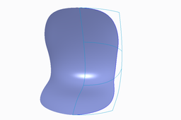
The completed part is shown below.

Set the working directory to the EXAMPLES folder and open the model CHAIR.PRT. (It can be downloaded from http://caeuniversity.com/courses/surface-modeling/)
Because this part is symmetrical so we will create half side of the part and then mirror it.
Required datum curves have already been created. You are encouraged to explore the way these curves have been defined after completing this exercise.
-
Step 2: Creating the surface
We will create a boundary blended surface by using the predefined curves.
Pick Boundary Blend icon.

The dashboard will appear as shown below.

Select the curves, while holding down the Ctrl key, in the order shown in figure below.

Pick in the Second Direction Collector to activate it and while holding down the Ctrl key, select the curves shown in figure below.

Apply the Normal constraint for the chain that lies on RIGHT datum plane as shown below.

This surface will be mirrored about RIGHT datum plane. Therefore to maintain tangency between original and mirrored surface, the surface has been constrained Normal to the RIGHT datum plane.
To make the mirrored and parent surface tangent to each other, we need to make the parent surface normal to mirror plane.
Pick Apply and Save icon to complete the feature.
-
Step 3: Creating the Datum Curve for Trimming
Now we will create a datum curve that will lie on the surface we have created and then trim the surface with this curve. First we will create four datum points to be used as reference for the datum curve.
Pick Point icon on the Model tab to invoke Datum Point tool.

Now pick on the surface near bottom right corner. Look at the position of mouse pointer in the figure below.

Pick in the Offset references collector to activate it.

Now select the edge shown in figure below as offset reference.

Enter 45 as the Offset value.

Hold down the Ctrl key and select the side edge as second offset reference.

Enter 25 as the Offset value as shown below.

Pick OK to complete the definition of datum point.
Now we will create another datum point so again pick Point icon on the Model tab.
Pick the following datum curve as reference.

Pick Next End icon to change the measurement reference to right end of curve
Change the Offset option to Real and enter 55 as the Offset value as shown below.

The preview will appear as shown below.

Pick OK to complete the definition of datum point.
Again pick Point icon on the Model tab and select the following datum curve as reference.

Change the Offset option to Real and enter 25 as the Offset value as shown below.

The preview will appear as shown below.

Pick OK to complete the definition of datum point.
Again pick Point icon on the Model tab and pick the surface near top right corner. Look at the position of mouse pointer in the figure below.

Pick in the Offset references collector to activate it.
Now select the top edge of surface as offset reference.

Enter 35 as the Offset value as shown below.

Hold down the Ctrl key and select the side edge as second offset reference.

Enter 35 as the Offset value as shown below.

Pick OK to complete the definition of datum point.
Now we will create a datum curve using through points option, passing through the four points that we just created.
Pick Curve through Points icon on the Model tab to invoke Curve through Points tool.

Pick the following vertex as first point for curve.

Pick the datum points one-by-one in the following order, PNT4 > PNT5 > PNT6 > PNT7

Pick the following vertex as last point for curve.

Pick Placement to access the Placement panel and check the 'Place curve on surface' option.
As the Surface collector becomes active so pick the surface as shown below.

'Place curve on surface' option is used to create a spline curve that passes through the selected points and lies on a specific surface patch.
Now we will specify the normal constraints for the ends of the curve.
So pick Ends Condition tab and change the End condition for 'Start Point' to Normal.
Now system wants to know a reference to which the new curve will be normal, so select the RIGHT datum plane as reference

Change end condition for 'End Point' to Normal and select the RIGHT datum plane as reference.

If you look at the end of curve, you will notice that it is twisted as shown below.

It is due to the wrong direction of normal constraint. So pick Flip icon to reverse the direction.
Pick Apply and Save icon to complete the feature. The datum curve will appear as shown below.

-
Step 4: Trimming the Quilt
Now we will trim the quilt with this curve. So first select the quilt.
Pick Trim icon on the Model tab to invoke Trim tool.
Select the newly created datum curve as trimming object and preview will appear as shown below.

Pick Apply and Save icon or middle-click to complete the feature.
-
Step 5: Mirroring the Quilt
Now we will mirror the quilt so first select the trimmed quilt.

Pick Mirror icon on the Model tab to invoke Mirror tool

select the RIGHT datum as Mirror plane.
Pick Apply and Save icon to complete the feature. Part will appear as shown below.

Now you can merge both surfaces together.
Select File > Save to save the work done so far.

