

Getting your Solidworks drawing lasercut ready

Hello everyone,
In this tutorial, I will explain and give tips for converting your Solidworks drawing to a vector file that CNC machines can read. I will be focusing on a laser cutter in this tutorial.
I will be using Solidworks and Adobe Illustrator in this tutorial. This is paid software if you want to use free software I recommend using Fusion 360 for 3D modeling and Inkscape for vector image editing.
If you have any questions or are missing information in this tutorial please leave a comment below so I can update the tutorial.
-
Step 1: Making a template
First I always like to make a template that fits the materials processing envelope (workarea) of the CNC machine I am going to use.
If you already made a drawing jump to step 2.
The first is to go to solidworks and select make a drawing.

Now we want to change the sheet size to the workarea. I am using a VLS4.60 so my workarea is 610mm x 457mm.

Your sheet should look something like this. Right click sheet1 and click properties.

In this screen we will have to change the scale to be 1:1. I also change the sheet name to the machine I am using.

Your template is now done. I recommand saving it somewhere so you can use it for other projects as well.
-
Step 2: Altering an existing drawing.
If you followed step 1. There is no need for you to follow this step.
In this step we will remove existing border from the standard sheets used in Solidworks. In my case I am using the A4 sheet size.
Right click your sheet and click on the edit sheet format option.

Press crtl + a and delete.

Now hover your mouse over the border and right click the delete option.

We now have a clean sheet.

now edit the properties of the clean sheet to the workarea of your CNC machine.

Let's move to step 3
-
Step 3: Solidworks settings
Let's now make it easier for ourself by changing a few solidworks settings.
First thing is changing the border colors.
Most laser cutters have this color code.

We don't want use black for our lines because this is only used for area's. You want to choose a border line color that is going to be used most in your drawing. Most often there are more lines for cutting than strokes. In my case I will select red because I only need to cut.
Select options in the top of your screen.

In system option select the colors tab. There we want to select visible model edges. Now click on edit to change the color.

Here we select the color we want to use.

We are now ready to go to the next step.
-
Step 4: Editing the drawing
Let's add a model to our sheet.

When we add a model make sure it has the right orientation and scale. For the scale you can use either the sheet scale we previously set to 1:1 or we can set our custom scale to 1:1.
Make sure to check the scale after you have placed the model. Because solidworks has a bug where it sometimes doesn't pick the right scale. You can check the scale by clicking on the model.

When you have placed all your models press ctrl + a to select all center marks. Now press delete to remove them.

Your drawing is now done.
-
Step 5: Converting the file
We want to convert our Solidworks drawing to a file that can be read by vector editing software. Therefore we need to save our Solidworks drawing as DXF.

Now select the option button.

Change the version to R13. In this screen we can also select it to export all our sheets to seperate DXF files. For that go to export all sheets to seperate files.

Now save the file. Let's go edit the DXF.
For this I chose to do it in Adobe Illustrator. But Inkscape (which is free) works great as well.
-
Step 6: Illustrator settings
Let's some settings. I appoligize for my version being in Dutch.
Go to edit/preferences/units

Now set your units to the units used in your Solidworks drawing.

Our settings have now been edited.
-
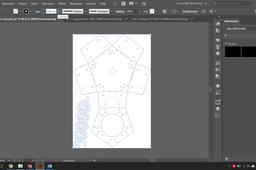
Step 7: Editing the DXF
esLet's open our DXF in Adobe Illustrator.

Now set it to the following settings.

Always check if your drawing has been scaled right. This can be done by selecting the line tool and going from point to point from a vertices that you know the length of.

Let's setup our palet with some of the CNC colors. The left square is for you fill and the right square is used for lines.

I will be adding blue since I already have red and black.

Now let's delete the watermark that came with our drawing.

We need our model to fit the artboard. For this we select the option.
Artboard/Fit Illustration

If you have overlapping lines you should go to step 8 first.
I know want to mark my engravings by filling them with a greyscale color. To do this we select all by pressing ctrl + a and go to Active paint/Make.

Let's get painting! Select the paintbucket tool. By right clicking on the shown tool.

Select a greyscale color by clicking on the fill color square.

Click all the parts you need to engrave.

Now we want to remove the red lines because we don't want our engraving to be cut out. For this we use the direct select. This can be used to change all strokes individualy. So this also works when we want to make something blue.

Select the lines you want to change. Sometimes you can't select all the lines you want at once. In this case use alt + leftclick to select the individual lines.

Select the stroke color to be none.

To make our CNC machine work accuratly we want change the stroke thickness to something small. I always choose 0,001mm. Make sure you use a comma. Press ctrl + a and change the stroke thickness.

Yeaaaah. Our drawing is now ready to be cut. This is the end result.

-
Step 8: Overlapping lines
In some cases you might have overlapping lines in your drawing. This is one my examples of the raspisistent. Because I have made the drawing by converting the assembly. My lines have overlapped.

In adobe illustrator we want to group the object.

Then we want to use the pathfinder tool. It can be found in Window/Pathfinder

Here we need to select the outline tool. This will remove any overlapping lines.

You will notice that the stroke thickness and color will be reset. Press ctrl + a and edit the stroke thickness to 0,001mm (or the stroke thickness recommended for your CNC machine). Or do this later because it makes it hard to see the lines.
Also don't forget to color the lines. Press ctrl + a and set the second square to red.

You should now be done with your drawing. Unless you still have to make strokes or engravings in this case go back to step 7.
-
Step 9: Other helpfull sources
Video about conferting Solidworks drawing to Lasercut ready
www.youtu.be/hZrGLonrpt8
I hope this tutorial was helpfull. Please let me know when thing can be improved.
Video about removing duplicate lines
www.youtube.com/watch?v=hcIKxlJTPxM
Step 7 of this tutorial might be interisting if you want to have a really tight fit for you laser cut.
http://www.instructables.com/id/Tutorial-Laser-Cutting-from-Solidworks/
Good luck with you project.
