

How to 3D Print a Detailed & Accurate Model of the Earth

Learn how to create a realistic 3D textured model of the Earth using Rhino, GrabCAD Print and Stratasys 3D printers. I also review how to select the right part priority and how to test prints for the perfect color.
-
Step 1: Prepare the Texture Images
Download the model here on the GrabCAD Community to print right away.
You can skip to Step Three using this pre-made model.
If you're interested in how I made the model, keep reading so you can learn to design something like this yourself.
NASA’s Blue Marble project is where I got the bathymetry and topography data from.

Topography tells us the height of the mountains on land, relative to sea level. Shading indicates changes in slope or elevation. The relief shading in this topographic map comes mostly from elevation data collected by space-based radars.
Notice the palest parts of the image - the white line of the Andes Mountains down the eastern coast of South America, and the pale white patch of the Himalayan Plateau. You will also spot that Antarctica and Greenland have a relatively high elevation compared to other land masses such as Australia - this is due to their layers of ice.

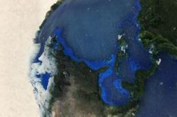
Bathymetry tells us the depths of different parts of the world’s oceans. As NASA explains, bathymetry is the underwater equivalent of land topography.
In the maps they provide, blue to white shading indicates changes in slope or depth, from -8000m to 0m (surface). The land is coloured black. You can spot the famous Mid-Atlantic Ridge as a paler line down the middle of the Atlantic ocean, and the Marianas Trench as a patch of deeper blue off Japan.
I combined the two maps in Gimp, a free photo-editing tool, to make a black and white bump map to define the model’s surface.
First, I converted the bathymetry image to Grayscale, to remove the blue tones:

Then I inverted the colours of the bathymetry, so that the land was white rather than black:

For the topography map, I altered the contrast so that the mountains were less pronounced compared to the rest of the land.
Then I combined the two images as layers, one on top of the other. Using GIMP’s Select By Color I was able to erase the land portions of the bathymetry map to transparency, so that the topography map image could be seen through them.

Finally I used Gimp’s Alpha Separation tool to make sure the sea layer occupied the lower 50% of the grayscale tones, and the land layer the upper 50% (so the sea would definitely map to indentations rather than outward features).
For most parts of the globe this was not so important. However, there are some land areas which are very close to or even slightly below sea level, such as Florida and the Netherlands. I wanted to make sure they weren’t covered by water in the model!

Finally, I did some manual editing with the paintbrush tool to remove any remaining black lines around the continents. This gave a smoother shading for coastal shelves so that these gradually disappeared beneath the ocean layer rather than dropping down abruptly.
-
Step 2: Use Rhino to Make a Textured Model

I made a sphere in Rhino and added a spherical ‘Closest point’ spherical Texture mapping to it, to translate between 2D images of Earth and points on the sphere surface.

Then I used Tools --> Apply Displacement to add our displacement map to the surface of the sphere, mapped onto the sphere using the texture mapping I had just defined.

I used a bump map made from the combination of bathymetry and topography, as described above. Obviously this wasn’t mapped onto the sphere to scale -- that would be rather hard to see as it would give a very smooth surface!
Instead, I exaggerated the depth of the seas and the height of the mountains to make the Earth model interestingly textured to the touch and visibly bumpy. I had to do an equal indentation and extrusion, to match the 50% sea / 50% sea grayscale mapping I did for the bump map.
In reality, the ocean is a bit deeper than the mountains are tall; Everest, the tallest mountain on Earth, is about 8,848 m high, whereas parts of the Marianas Trench are as deep as 10,994 m. But it looked about right and gave the land areas a nice appearance.
Then I added a separate color texture by assigning Material by Object. This let me add a full-color appearance for the model so that you could see realistic tones and colors for the continents and seas.
For this appearance texture map I used another Blue Marble image, the “Blue Marble Next Generation” - a full-colour Earth map without clouds. I stretched this over the Earth model using the same mapping technique as the bump-map.

To add a sea to the model I made another sphere and gave it the same centre as the first sphere. I made the radius the same as the original sphere; because it had no bump mapping, it lay below the ‘land’ level of the first sphere and above the ‘seas’.
I did not map any textures to the sea but just used the ‘water’ material of Rhino to ensure a clear appearance that would reveal the details of the first sphere beneath it.

Finally, I made a third, larger sphere, again with the same centre, out of completely clear material. The larger sphere enclosed the first two model spheres.
I applied an image texture to this sphere for the clouds, using NASA image “Blue Marble Clouds” . I edited the image first in GIMP to turn the black areas transparent so the Earth could be seen through the gaps in the clouds.

With 100% transparent material base material of the sphere, this gives the effect of a cloudy atmosphere floating above the surface of the Earth. I dialed transparency down to 17% so the clouds could be seen in this image, but it was exported as a VRML with 100% transparency on the cloud sphere object.
The cloud-sphere is optional; the model printed quite well without it, and some people preferred the ability to feel the textures of the continents under their hands. It’s quite satisfying to run your finger down the spine of South America! However, I thought it would be useful to include it for reference for people who are making full solar-system models, as it makes the Earth model appear more like the famous ‘Blue Marble’ images of Earth from space.
-
Step 3: Test Prints
In the Cambridge office we didn’t have a Stratasys J750, so we had to do our trial printing on an Objet 260, which only handles 3 colours of material at a time + support. This meant I couldn’t test transparency and full colour together, which made testing print accuracy a bit trickier.
We also ran out of yellow material so I couldn’t test a full-colour print at any point but had to rely on the renderings in GrabCAD Print to check the appearance of the final models. It meant that I performed more test prints than would be needed, as I couldn’t print every feature together.
Because I had to make multiple printing trials, I printed my Earths at reduced size, to save on materials, which is generally good practice with a new model. On the first ⅓ size print with transparency, the oceans appeared OK after a little polishing with sandpaper.
I exported the models for this from Rhino as two separate STLs (since I couldn’t do full colour anyway) and that way it was easy to assign each to have a different material.

(This print was the one which convinced us the topography was sound)
For the final print, I used the J750 in our Boston office and they sent over the resulting parts. Thanks guys!
-
Step 4: Set Part Priority in GrabCAD Print
Inside GrabCAD Print, there’s an important setting you can use when printing models like this with overlapping shells: Part Priority. I used this to make sure the different bodies of my model were given the right priorities by the slicer.
You need to change the relative priorities for this model. The default priority for multi-shell bodies which overlap when printing on PolyJet machines is based on their bounding volume, so that inner shells have priority.
This is usually a fine approximation, but our earth sphere has a larger bounding box than the ocean sphere (because of the mountains). So if we don’t change the priorities, the slicer will want to assign a transparent core for our model based on the ocean sphere, which isn’t correct. It would make our Earth model look like it was entirely made of water with some floating pieces of land on top.

To access Part Priority, you’ll need to enable the Advanced Slicer and then switch on "Show assembly structure for VRML and OBJ files" in the Preferences menu of GrabCAD Print. You may need to restart the application after selecting these Preferences.

Then, when you import the model, you will see that it is an assembly made up of three separate bodies - the ocean, the land and the atmosphere. Each of them can be clicked on individually and its Priority changed.

If you right click on a body, you’ll see which one it is because of the highlight, and you can select “Part priority” from the drop-down menu and update it. You’ll see circled numbers appear in the part tree to show you the new priorities. Make sure the earth body has Priority #1, a superior priority than the ocean body.
-
Step 5: Finish Your Final Print
If you decided to print the model with a clear atmosphere layer, this will need some post-print finishing to give the best looking final effect.
I set my print to ‘matte’ effect so that it would be one surface-finish all over and therefore easier to sand.
First, remove the support material and give the model a gentle scrub with water. To give a nice shine to the surface and allow you to see through the transparent material of the atmosphere, wet-sand the surface using progressively finer grits of sandpaper, moving the model in gentle circles across the surface of the paper.
Be patient - this can take a while!
The model will have a duller appearance when it dries, but you will know you are done with sanding when wetting it allows you to see clearly through the atmosphere layer and the surface feels smooth to the touch. I recommend adding a surface coat of clear resin to make the model look great and keep it pristine after sanding is done.
Quick note: Using ‘glossy’ effect so that half the sphere is already polished-looking may be tempting, but it can create a discontinuity between the appearance of the two parts of the sphere that is a bit harder to fix up.
- Learn more on the two finishes: Matte or Glossy?
-
Step 6: Enjoy!
The most difficult aspect of this project was probably getting to grips with Rhino’s texturing tools. Watching video tutorials was very helpful with this as it presented the UI in a way that online documentation alone couldn’t match.
Even better, find someone who is already familiar with it and take a look over their shoulder. Once you are comfortable with the modelling process, this technique can be used for all kinds of interesting things, such as showing geographic data of national parks or even making a whole solar system!
If you like you can download the model I made here on GrabCAD Community for inspiration.
I really enjoyed the process and getting to hold the final model (and to wear it as a pendant!) was incredibly satisfying. Thanks again to my colleagues who helped teach me these tools and how to use the J750 best. Next, the moon!

