How to Go from 3D Scanning to 3D Printing

A 3D scanner is a device that analyzes and captures the geometry and colors of physical objects to transform them into digital 3D models. The scanning process collects sample points from the object’s surface and generates its geometric shape through extrapolation. There are many different 3D scanning technologies and each one comes with its own advantages, limitations and cost. Stratasys tested two types of Creaform 3D scanners: the HandyScan 700 and the Go!SCAN 20. These portable 3D scanners can be used for a wide range of applications, offering a simple and intuitive scanning experience, providing fast and reliable results.
The Go!Scan 20 scanner can capture 3D data in color. It provides a very fast measurement rate and requires minimal data post-processing. The HandySCAN 700 is used mainly for taking measurements and reverse engineering. This scanner is fast at delivering accurate and high resolution 3D scans while remaining simple to use.
All phases of product design, from concept through manufacturing, can benefit from the workflow combination of 3D scanning and printing. This process can reduce the number of design iterations and the time between each, lowering the total cost of each prototype.
The following is brought to you by Stratasys:
-
Step 1: Scanning Options
3D scanners can be divided into two categories, each relevant to different applications and types of scanner.
1.1 Scan for Color
Whether you’re scanning a part for prototyping, educational or medical purposes, you can use a 3D scanner to digitize an object’s shape and colors and print it using a color 3D printer. The final result will have the same geometry and color as the original and enable you to print additional copies.
1.2 Scan for Inspection
Scanning parts for inspection allows you to find defects in the surface finish or compare printing results with the original CAD file. In both cases you will have to scan the objects at a high resolution.
Although the reasons for scanning might be different, the process is very similar and requires the same operational methods.
-
Step 2: Softwares
VXelements including VXmodel and VXinspect InsightTM software Objet Studio PolyJet Studio -
Step 3: Preparation for Scanning
2. 1 Scanning Glossy, Translucent or Dark Objects
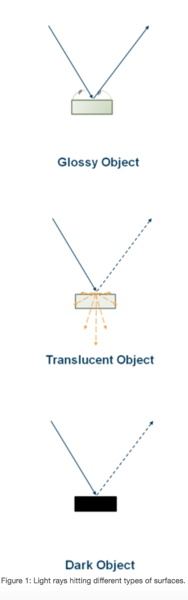
Scanning glossy, translucent or dark objects can be problematic because of the way light interacts with the part’s surfaces. For glossy objects, light reflects at an angle equal to the incident angle, resulting in only small amounts of light being collected by the scanner. For translucent objects, light doesn’t reflect off the surface but is instead scattered throughout the volume of the part. For dark objects, most light is absorbed by the object’s surface rather than reflected.
Scanning an object that has one or more of these characteristics might result in undesirable scan data.
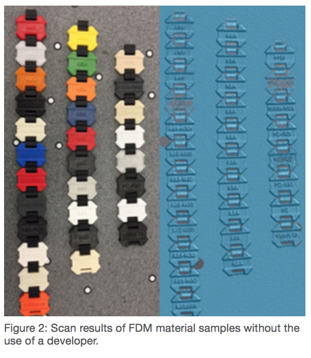
To overcome these issues, spray the object with a water-soluble anti- reflective powder such as Magnaflux Spotcheck SKD-S2 Developer. This allows the scanner to pick up the object’s detail. The developer makes translucent parts opaque and glossy parts matte. It is also possible to cover the object with talcum powder if an anti-reflective developer is not available.
After the scan is finished, remove the developer from the part with a damp cloth or penetrant cleaner, provided it’s not solvent-based.
The use of developer is effective when trying to capture the shape of glossy, translucent or dark objects, but results in muted colors when trying to reproduce the original color
-
Step 4: Choosing the Correct Resolution
Before starting the scan, it’s important to understand the purpose for scanning, to set the relevant parameters. One of the most important parameters is the scanning resolution, which represents the smallest feature detectable by the scanner. For example, a 0.2 mm (0.079 in.) resolution means that any object smaller than 0.2 mm will not be identified and collected. The available resolution might differ among scanners and can be adjusted in the scanning software.
Some other parameters to consider are:
1) Part detail - the more detailed the part is, the higher resolution required to collect all of its information. For example, large and flat parts, or parts with simple geometry can be scanned using lower resolution.
2) Application - each application requires a different level of detail and, therefore, a different resolution.
-
Step 5: Adjusting the Scanning Resolution
During the scanning process you can change the resolution to obtain the accuracy you need. After scanning the entire object, you can scan specific areas with higher resolution.
To achieve the best results, the scanning resolution needs to be adjusted to the surface being scanned. Even within the same object, there might be areas that need to be scanned with different resolutions.
When scanning a large area without unique characteristics, the scan resolution can be lowered to decrease scanning time and file size. The recommended resolution for this type of scan is about 1 mm (0.039 in).
For objects with fine features and/or complex geometry or sharp corners, use high resolution. This will increase scanning time and file size but allows you to capture all of the object’s details. The recommended resolution for this type of scanning is 0.2 mm but can vary depending on the scanner.
-
Step 6: Scanning Color Objects
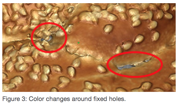
After scanning a model and before sending it to print, make sure that it is watertight – meaning it has no holes or open shells. Scanning and processing a colored model is more complex. Creaform has developed software called VXelements that allows you to collect, analyze, and edit information from a 3D object. This software also offers an option to close small holes during the scan, but sometimes there are holes that cannot be closed. In these circumstances, use VXmodel or a third-party software such as Magics or Deskartes, which have the ability to close holes and prepare models for print.
Be aware that fixing holes with other software might result in broken or missing textures, non-uniform textures and drastic color changes near the fixed hole. To correct this, import the texture file into design software such as Photoshop and edit the problematic areas.
-
Step 7: Enhancing the Colors of a Scanned Object
When scanning a colored object with the intent to print, you will sometimes want to change or enhance its color results. If you wish to change the part’s color or texture, you can use the UV map that was generated after the scan. A UV map is an image of the part’s 3D geometry unwrapped into a 2D image, including the colors and textures. After the scan, the VXelements software creates a UV map that can be exported along with the part’s mesh into a third-party design software, such as Photoshop, where the texture can be edited.
Here are some examples of scanned objects made using Creaform Go!SCAN 20, and their printed versions (Figure 4).

-
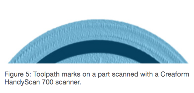
Step 8: Setting the Correct Resolution for Inspection
When scanning a part for inspection, use the highest resolution available for the scanner that is sufficient to inspect the part. At this resolution you will be able to capture all the details of the scanned object.
-
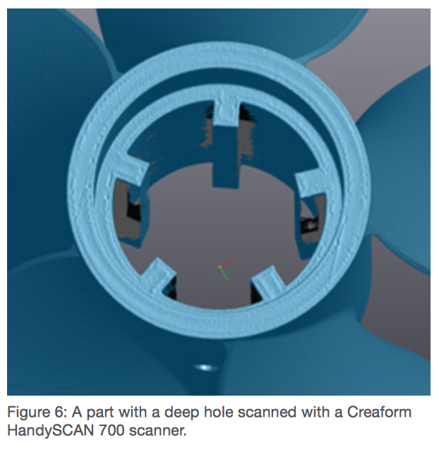
Step 9: Depth Limitations
One of the advantages of 3D printing is the ability to print complex geometries. When trying to scan deep holes and crevices, some scanning technologies will encounter problems collecting data in those areas. This is due to the design of the scanner and the distance between the scanner’s cameras (the two cameras have to be able to see the same area in order to collect data from the part’s surface). Each scanner comes with its own limitations, including size and depth of readable holes. Even though you are not able to collect all the information from the hole, the data collected from the scan can still be used for inspection of the part or can be filled for reverse- engineering purposes.
-
Step 10: Comparing a Printed Part to its Original CAD File
After scanning a part for inspection, VXinspect software can be used to compare the scan with the original CAD file, to determine whether the printed part is identical to the CAD model.

-
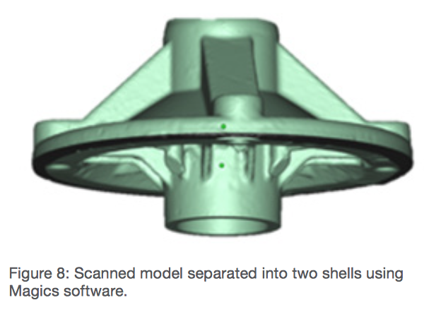
Step 11: Separating the Scanned Model into Different Parts
Sometimes after scanning an object there is a need to separate it into different shells to print them in different materials using PolyJet 3D Printers. This process can be done using different software packages such as VXmodel or Magics. After saving the shells as STLs, import them into Objet StudioTM or PolyJet StudioTM software as an assembly and assign your desired material to each shell.