

How to model retainer cage of ball bearing?

Slightly more complicated (yet much more realistic) way to build a retainer cage <link>.
To build this model, i assumed, that:
- bearing inner diameter = 20 mm;
- bearing outer diameter = 40 mm;
- ball diameter = 6 mm;
- # of balls = 8;
- thickness of the retainer = 0.5 mm.
Besides, i decided to make it a multi-body part, but surely, it can be made like an assembly.
Also, the model is built with zero tolerances and without "cosmetic" elements (like fillets, chamfers, etc.), that should definitely present in real detail.
So, here is the procedure:
-
Step 1:
Extrude a round plate (i use to call it "a pancake" :) up from the top plane). The sketch diameter is not significant, but it should be greater or equal to the outer diameter of the bearing.

-
Step 2:
Next, on the front plane, we should draw a very simple sketch - a 90-degree arc with radius equal to the same of the ball, and revolve a thin-featured element. Be sure to UNCHECK "merge result" at this point!

-
Step 3:
Now, a cut-revolve element should be used with the SAME SKETCH as in Step 2, to eliminate the "bottom" of the previous element.

-
Step 4:
The simplest sketch ever - just an axis line :). Front or right plane - never mind. We will use this sketch several times in our model.

-
Step 5:
Circular array of the semi-sphere, using an axis from the previous step. Note, that "geometry array" option must be CHECKED obligatorily!

-
Step 6:
Combining the two bodies (cause we did not merge them at Step 2).

-
Step 7:
The sketch (on the top plane) consisting of two circles. Choose the diameters, minding that there must be some gap between the rings of the bearing and the retainer cage.

-
Step 8:
Cut-extrude, using sketch from previous step. Pay attention, that cut-off area must be OUTSIDE the distance between the circles of the sketch! (Sorry, i don't know, how this option is properly called in English, but there is only one check-box in command options, and it must be CHECKED).

-
Step 9:
(For multi-body part only. No need to do this, if you plan to make an assembly - in that case, you should insert another instance of the part in an assembly)
Mirror the BODY from previous step, using top plane as a mirror plane. Do not forget to UNCHECK "merge result" option!
-
Step 10:
Draw a sketch on the MODEL FACE and cut-extrude it downwards with "through all" condition.

-
Step 11:
Create circular array of the holes, using the sketch from Step 4 as an axis.

-
Step 12:
{Warning! Steps 12, 13, 14 and 15 are used to make a rivet. If you plan to make an assembly instead of a multi-body part, you should make a standalone model of this rivet and insert it into your assembly. Or, of course, you can use a standard rivet from SW Toolbox (if it is available). Therefore, these steps are described in short.}
The sketch (on the top plane) for this step is the projection of the edge of the hole, made in Step 9. Extrude it with the condition "to the face", using the same MODEL FACE as in Step 9.

-
Step 13:
Sketch the circle on the top face of the previous extrusion and extrude it upwards (it would become a rivet head further).

-
Step 14:
Apply a fillet to the upper edge of the previous extrusion. In order to make the rounded rivet head, the fillet radius should be 1/2 of the rivet head diameter.

-
Step 15:
Mirror the resulting body upon the top plane ("merge result" is CHECKED for now).

-
Step 16:
Perform a circular array of the rivets, using the sketch from Step 4 as an axis.

-
Step 17:
Finally... Voilà! That's it! :)

-
Step 18:
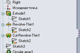
Not a step, just an appendix.
For advantage, I've made an additional screen-shot of the model tree. The names of the elements may be not the same that in English version, because i have a localized Russian version of SW, so i translated the names of essential elements myself...
