

How to Prepare Your 3D Model for Manufacture

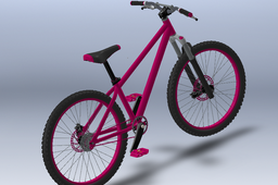
Using this ladies bike model found in the thousands of models available on GrabCAD I have made a step-by-step guide on how to break down your top level assembly for the workshop or for outsourcing.
-
Step 1: Nuts, Bolts and Fixings
Make sure your model is complete and a true representation of what you want to produce.
It is important that your model has all of the finishing touches because it's more than likely that you won't be present when your product is being produced. For example if you don't add every single fixing into your model they wont show in your Bill of Materials (BOM) therefore will not get ordered.
Most CAD packages have lots of quick ways to add in multiple fixings.
SOLIDWORKS has some fantastic functions for doing this.

Here you can see the drop down menu for the linear component pattern. These are all useful in their own way. These all work in the same way as their part level counterpart.
Also, smart fasteners can be an easy way of selecting which fixings to use.
 All you need to do is select any part containing a hole or select populate all and SOLIDWORKS adds fixings in giving you the option to adjust sizes in all of the groups it finds.
I have deliberately made the bolt too big for the thread when I hover my cursor over the error it gives me a warning.
I really like copy with mates which can be found in the insert components drop down menu.
Just mate in one of the components that you wish to repeat.

Once you have opened the copy with mates function select the component you just mated in you can also select multiple components, washers, nuts, etc.
After that the small arrow.

Then all you need to do is reselect the mates in the new locations and the component will appear in place. You have the option to reverse the direction of the mate. Once you're happy, select the green tick and go again.

Top tip : Create any fixings that mate together like a bolt/washer/nut as a sub-assembly saving you from mating them in individually.
-
Step 2: Feature Tree Structure
While building your assembly, it's important to structure your feature tree using sub-assemblies.
It can become very difficult to navigate through a long feature tree wasting time scrolling up and down plus you may not be the only person to use the model so make it easy to see how the model is put together at a glance.

You can see that the whole feature tree fits into one screen and it is clear to see what each sub-assembly/component is.
Top tip: If your feature tree happens to end up a little too long you can place items in a folder by using the Shift or Control key.
Select a group of items, right click on them and select add to new folder.

Then give your folder a name.
This is great for grouping multiple components together at top level or in a sub-assembly and also works at part level.

When building an assembly you should think of the process that it will actually be built.
So if an order for 100 of these bikes were placed you would probably put 100 rear wheels together in one go instead of building one whole bike at a time.
So keeping the rim, tire , sprocket and the rest of the components for the rear wheel together in a sub-assembly you can easily isolate these parts for drafting keeping bills of materials simple.
-
Step 3: Preparing Your Parts and Fabrications
It is crucial as a designer that all of your parts fit together as intended.
Check your design at Assembly level using the interference Detection, clearance verification, hole alignment, and the measuring functions.
The first three work in an almost identical way, for this case I will show the interference detection.

All of these functions can be found in the evaluation tab at assembly level.

You can either select between components of your choice or the whole assembly then select calculate.

Solidworks will then pick up where any parts intersect.
Sometimes a transition fit will be required like when modeling nylon bushes but in the case highlighted the seat post is clashing with the frame so both being made of steel this will need to be fixed by adjusting the parts to ensure a good fit. This is a good time to use the measuring for closer inspection.
These tool are great but only work at assembly level so if you if you have created any fabrications as a multi-body part like when using the weldments function these will need to be checked before the individual members are manufactured.

This frame is a good example. It has been created using the weldments and trim extend functions.
I have noticed that where highlighted the join between the members doesn't have the same black edge between them the others have.
Time to have a closer look.

When I select one of the members its clear to see that we have a clash.
A quick and easy method to fix this issue is to use the move copy bodies and combine functions.
Both very useful functions in many different situations.

In the direct editing tab you will find some excellent features for altering and manipulating your part bodies.
First we are going into move copy bodies.

Select one of the members then tick the copy check box.
We only need one copy and then select the green tick and OK in the dialog box.
I want the copy to remain in the same place as the original.
If you haven't used this feature before spend some time trying out the options its is a powerful function it will save you time in the future.
We now have two of the same members in the same space and an addition to the feature tree.

Now open the combine function.

In this situation we want to subtract the additional member we have just added from the one it's clashing with.
The main body is the one we want to keep, bodies to combine is the one that we are going to lose.
You will see SOLIDWORKS color codes the members.
When you're happy select the green tick.

You then get the option of which bodies to keep.
I have selected body one, body two is the excess material from the other member we don't want to keep that.
Try all the options you will get a preview when selected.
Then select OK.

Now the members fit together as they should so no issues when this frame goes through production.
-
Step 4: Know Your Production Limits
Keeping parts and assemblies manufacturable is key while designing your products.
It's good to research weather the materials you are working with are available in the sizes you need try to make the most of what you will be ordered (Lean Manufacturing).
The thoughts of transport should be considered how is it going to be packed and handled? Will it fit into a van or lorry?
Know the limits of machinery you have at your disposal for example, for air bending request or create a bend table.


The examples shown are an easy to follow guide on exactly what is achievable regarding bend radius, maximum material thickness, and flange length with particular tooling, but this dose vary according to what tooling you have available.

When creating CNC profiled parts, you should consider the maximum bed size of the machine you or your supplier has.
Adding fillets to every corner is good practice because the cutting machines don't like sharp corners and often will stop mid program.
Laser cutters can be accurate to 0.3mm
 CNC milling machines can do amazing things but they do have limits consider how is the tooling going to reach in to remove the material.
 Get as much information on the capabilities of equipment you have access to.

When creating fabrications make sure the location of the welds are accessible.
Welding torches can be quite bulky and the weld requires a good supply of the shielding gas to prevent oxidizing of the weld body .

This is just a few examples of the many different manufacturing processes out there.
The moral of the story is to get to know the processes you intend to use and maintain a good relationship with your suppliers, logistics, and production team.
Top tip : Any good engineer will have a Zeus pocket book.
It is brimming with useful information from tolerances to conversion tables to engineering terminology.

-
Step 5:

Please don't forget to like, share, and comment.
