

Lenticular Effects 1


An introduction to 3D printing lenticuuar effects. In our first design of this series we will look at creating an arrary of lenticular domes. This array will; be the basis for future projects in this lenticular series that will be printed on Fabric useing Polyjet Technology
-
Step 1: What Is the Lenticular Effect?
In its simplest form a lenticular effect can be used to change or shift an object or image color, design or messaging depending on the perspective of the viewer. This is typically used for aesthetic purposes but can also be used for marketing and labeling.
It works by placing a lens or a prism above an split or sectioned image. The
viewers point of view will define the section of the image that can be perceived

-
Step 2: How to Create a Lenticular Cell
For this we can use a range of software packages as the process steps will be the same. In this example I will be using Materialise Magics as I find it is better at processing the large multi body arrays than CAD (This might be more related to my computers capabilities than CAD limitations)
We will first start by preparing a single cell that will comprise:
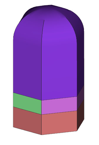
- White Base (optional but can be important when printing on dark substrates to ensure good color)
- Color layer this will be split into two or more segments to achieve the lenticular effect
- A clear section that will act as a lens / prism
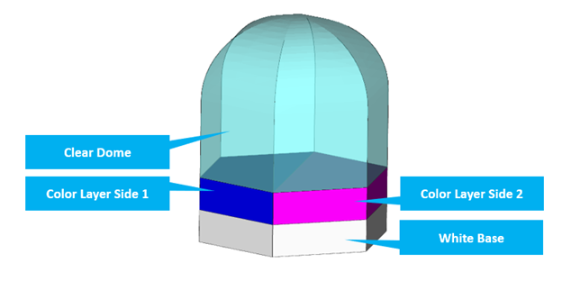
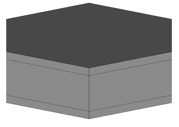
In this example I will be using a hexagon as my cell beacause when they are arrayed together, they leave minimal gaps between cells. However, you could use any base shape, circle / triangle etc.
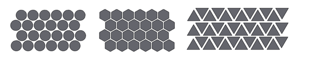
Additionally, these cells can be arranged in different configurations and patterns and even scaled in size across the array to increase the range of effects achievable
[1]
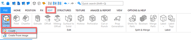
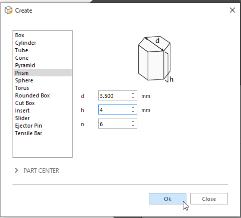
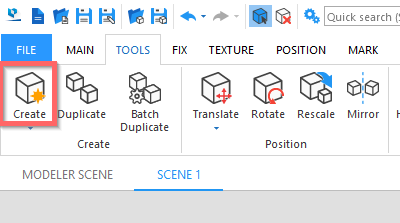
In Magics (Version 27) Go to
Edit > Create
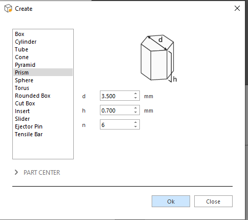
We will start off by creating the white base:
- Select Prism
- Number of sides =6
- and element dimensions. here i have gone for 1mm high (as some of the material will embed into the fabric) and 3.5mm diameter

- Click "OK"

[2]
Now to create the color layer we repeat the process
Edit > Create
- Select Prism
- Number of sides = 6
- However in this instance we will adjust our color layer to be 0.7mm high and 3.5mm diameter
- Click "OK"
[3]
Now lets raise this newly created element into position, navigate to
“Position > Translate”
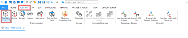
Ensure the color layer is selected in the parts list
- Raise the color layer by entering 0.85 in the “z” axis (The models are inserted in the middle of the ground plane, the value 0.85 is caluclated by talking half the height of each of the created models and adding them together)
- Click "Apply"
- Click "close"
[4]
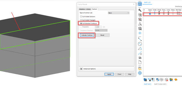
Now we go to multi section
And turn on the “y” axis plane visibility
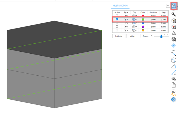
Now navigate to
“edit> cut or punch”
Now navigate to
“edit> cut or punch”
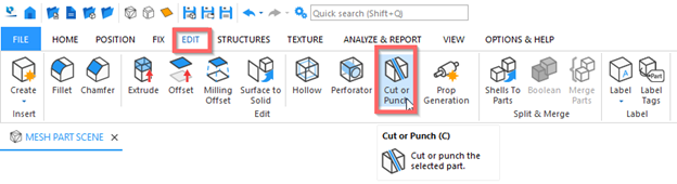
Ensure the color layer is selected
Select “indicate contours”
Select the contour on the color layer
Click “apply”
Click "close"
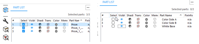
Let’s take this opportunity to rename the models we have in the parts list
This can be easily achieved by “double clicking” on the part name in the table to edit the name
[5]
Now we can create the clear lens dome
Navigate to:
Edit > Create

- Select "Prism"
- Number of sides = 6
- However, in this instance we will adjust our dome to be 4mm high and 3.5mm diameter
- Click "OK"

[6]
Now lets raise this newly created element into position, navigate to
“Position > Translate”
Ensure the correct object is selected in the parts list
- Raise the clear dome by entering 3.2 in the “z” axis
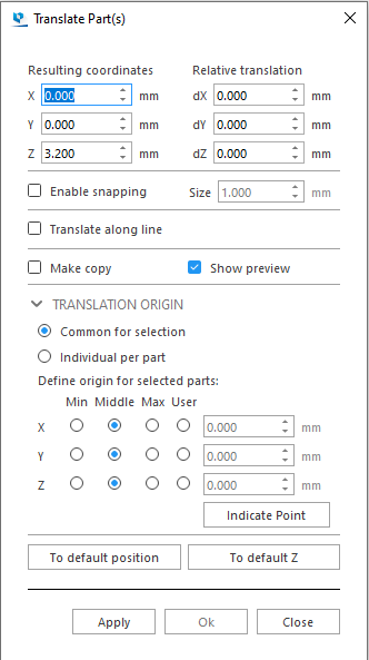
Click “apply”
Click”close”
Now we can update the part name and lets autocolor the models for ease of identification (dont worry we will assign materials / colors in GrabCAD print later)
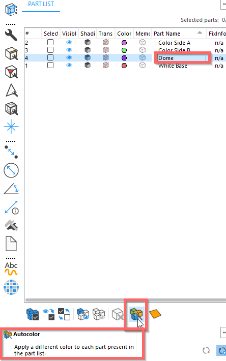
[7]
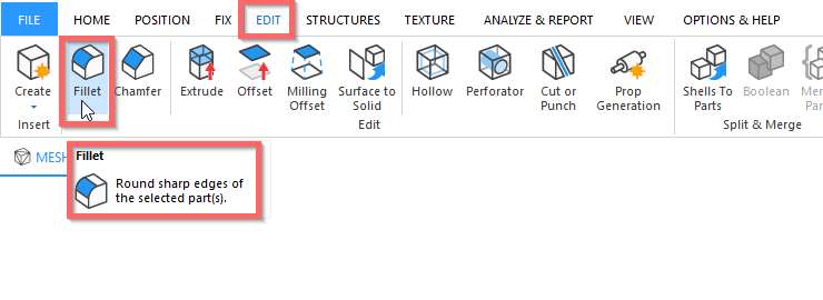
Finally let's add the dome to the top of our clear segment
Navigate to:
"Edit > Fillet"
Enter appropriate values, for this geometry I have selected 1.44mm as the radius and a high tolerance for a smooth non faceted curve.
Click “Indicate Edge”
Hold the “Alt” key whilst selecting the top contour
Click “Apply”
Click “Close”
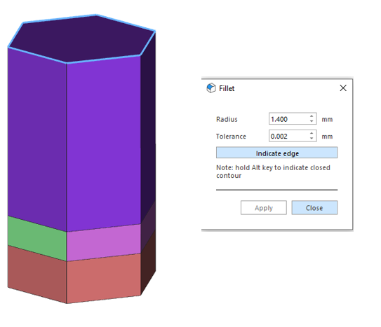
And now we have our completed lenticular cell
-
Step 3: Create an array of cells
First to help you create the right size of array for your needs I like to ceare a mock up of the size I need to fill.
For this example I will make a box 135 x 395 x 3mm
Click on the "create" tool
"Tools --> Create"
Input the required dimensions in the dialonge box
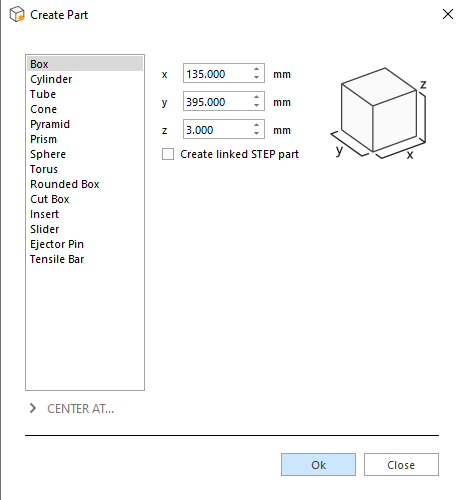
Click "OK"

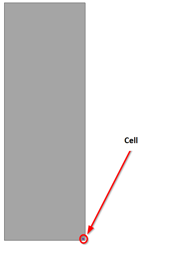
Now lets reposition the box so that its bottom corner is aligned with the cell

Manually move the model untill you are satisfied with the position
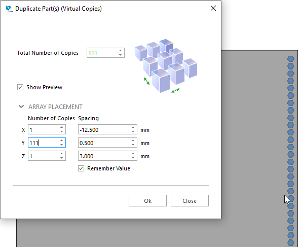
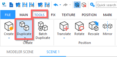
Now lets use the duplicate tool to create an aaray
Select all the cell models

Click "tools --> Duplicate"

Enter the following values to duplicate in the y axis
Now go back to the translate tool

- Ensure all the bodies are selected (except for the box_
- ensure make copy is selected
- move the copied bodies
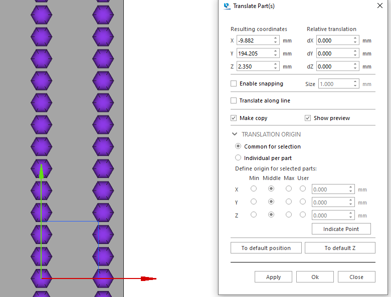
- Deselect the make copy
- fine position the models with the same spacing as applied in the duplicate (0.5mm in this case) either by using the relative translation field or manually by dragging on the positioninig arrows
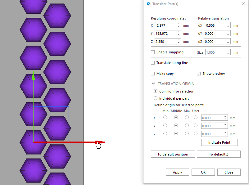
Select all the bodies (not includiong the box)
and duplicate in the x axis
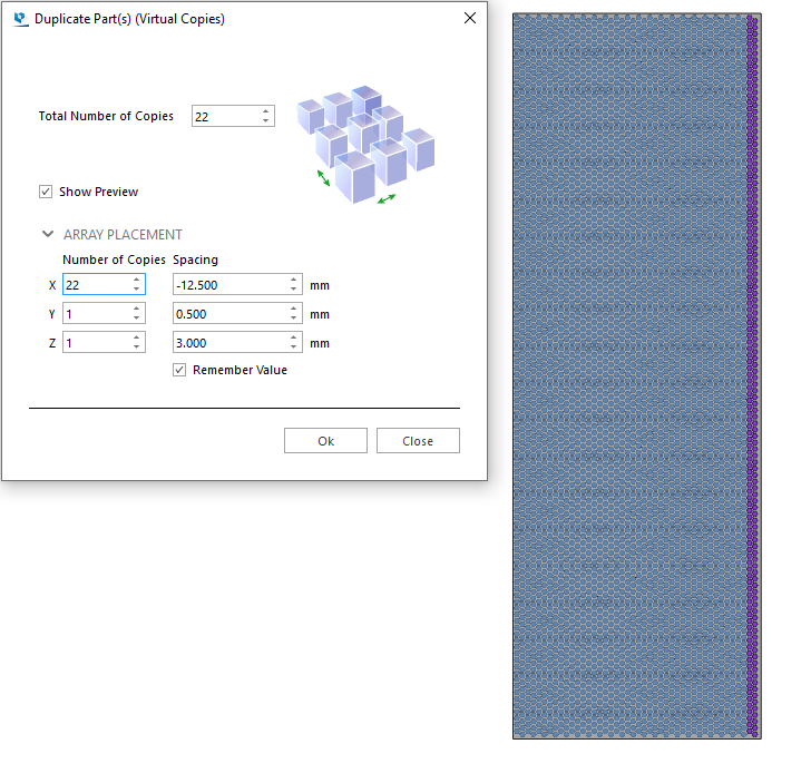
Click "OK"
Wait a few minutes
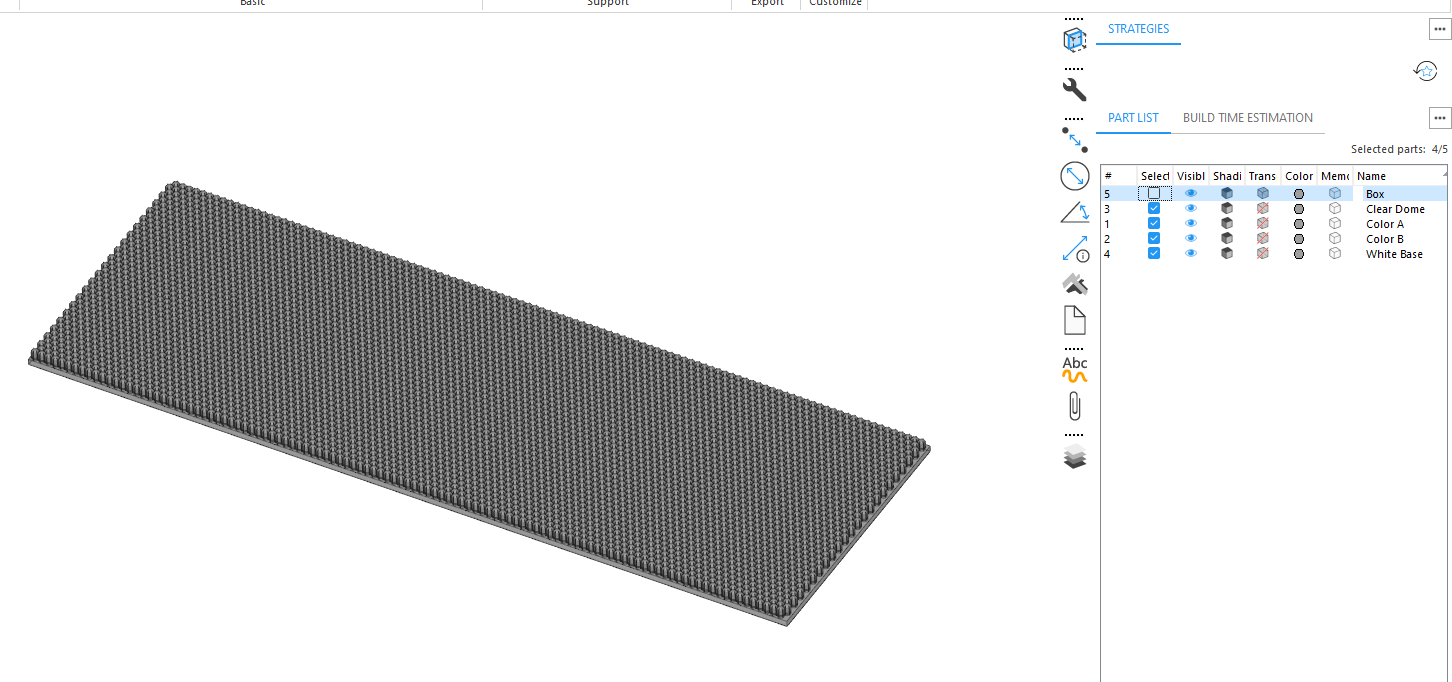
Now go through all the modles in the parts list and group them acording to name.
select the models with the same name
- Slect the first one in the list
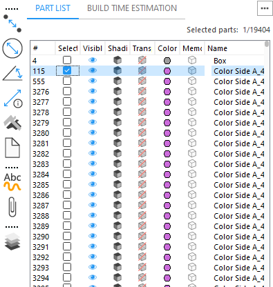
- scroll down untill you see the last one with the same name
- hold shift and select that item
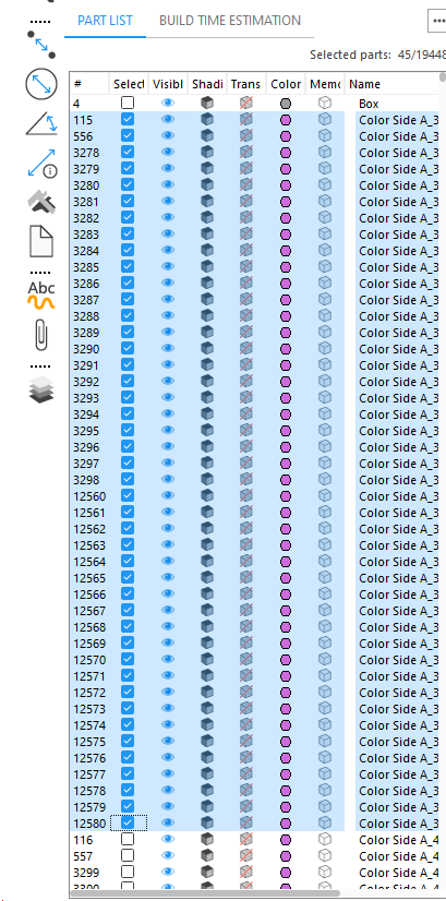
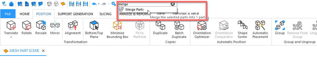
- click on the merge shells button
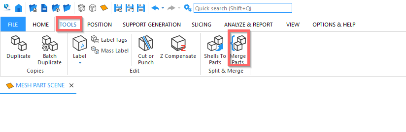
- Or type "merge" into the search box
The result:
-
Step 4: Print on fabric
Seklect the models that wo wish to export (all the models excluding the Box)
Go to:
file --> Save --> Save selected models as
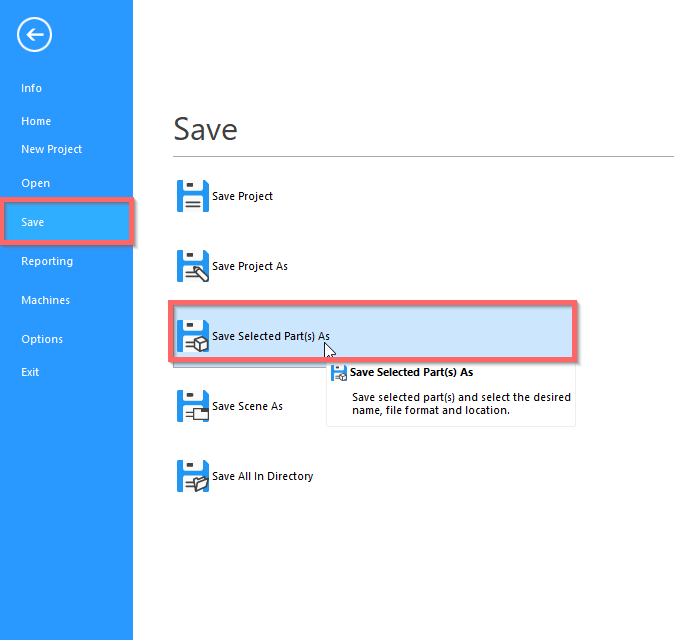
In the file explorer choose a folder to save the files to
Click "Save"
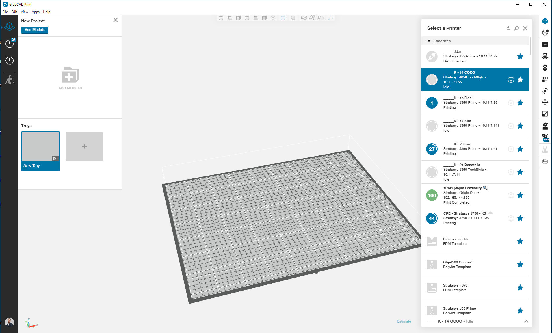
Oprn GrabCAD Print
Select a PolyJet 3DF printer
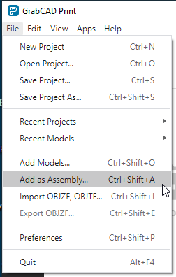
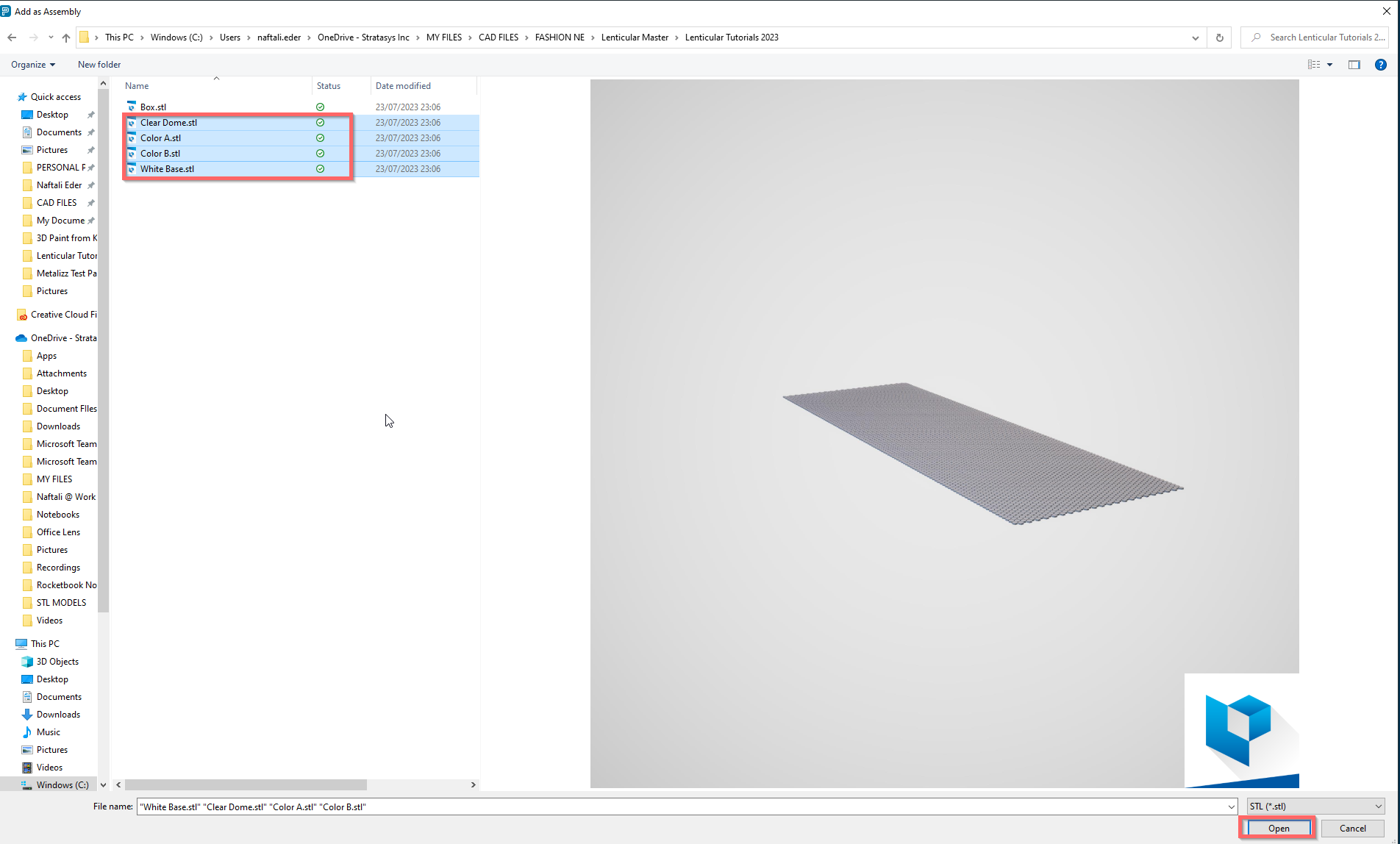
Import the saved files as an assembly
"File__> Add as Assembly"
Navigate to the models you saved select them all and click "Open"
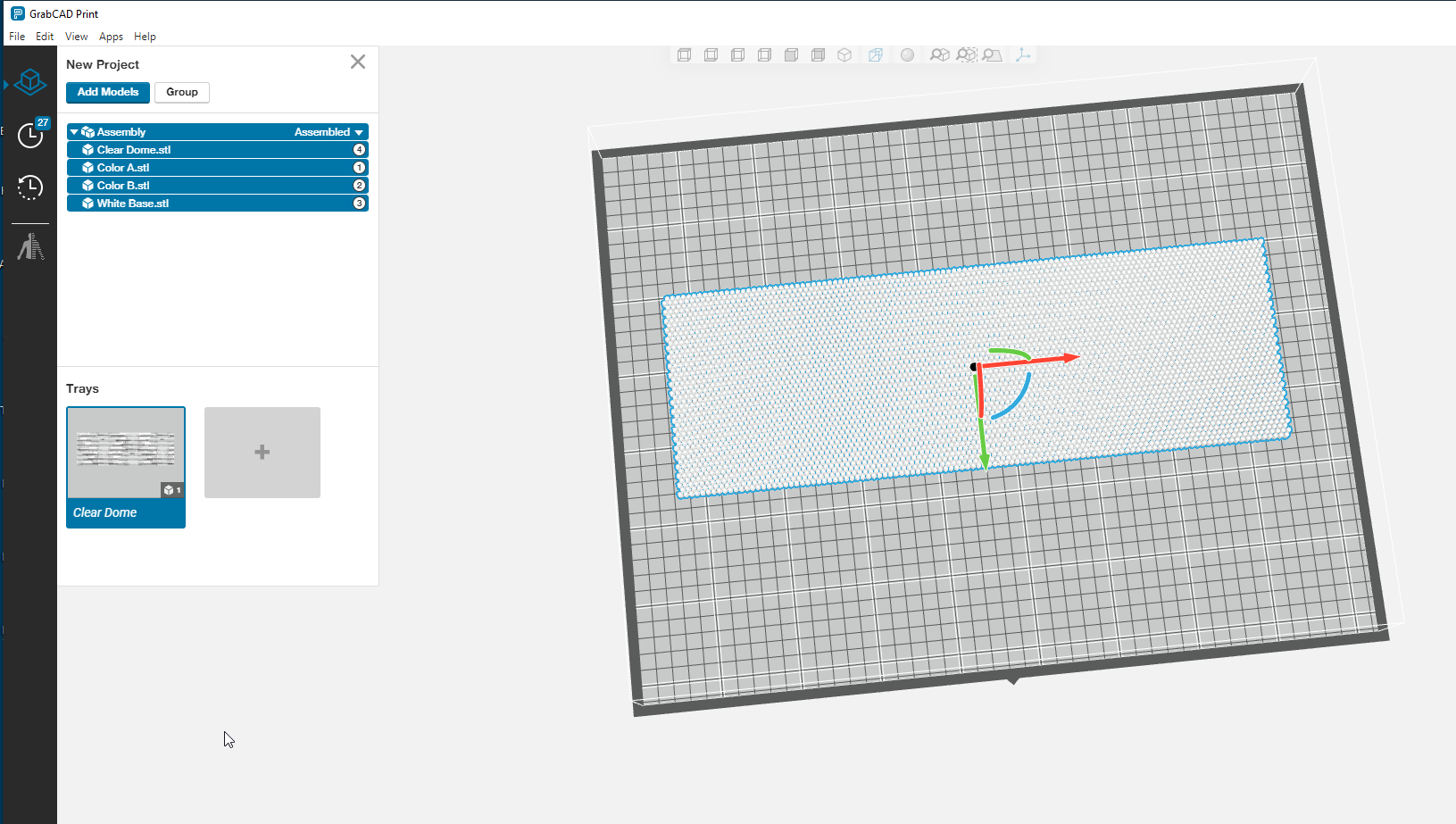
Orientate the part so that it is in the right orientation

You can position manually using the gimbal if required
Assign materials to each mesh by selecting them in turn and making the appropriate material selections from the model settings plane
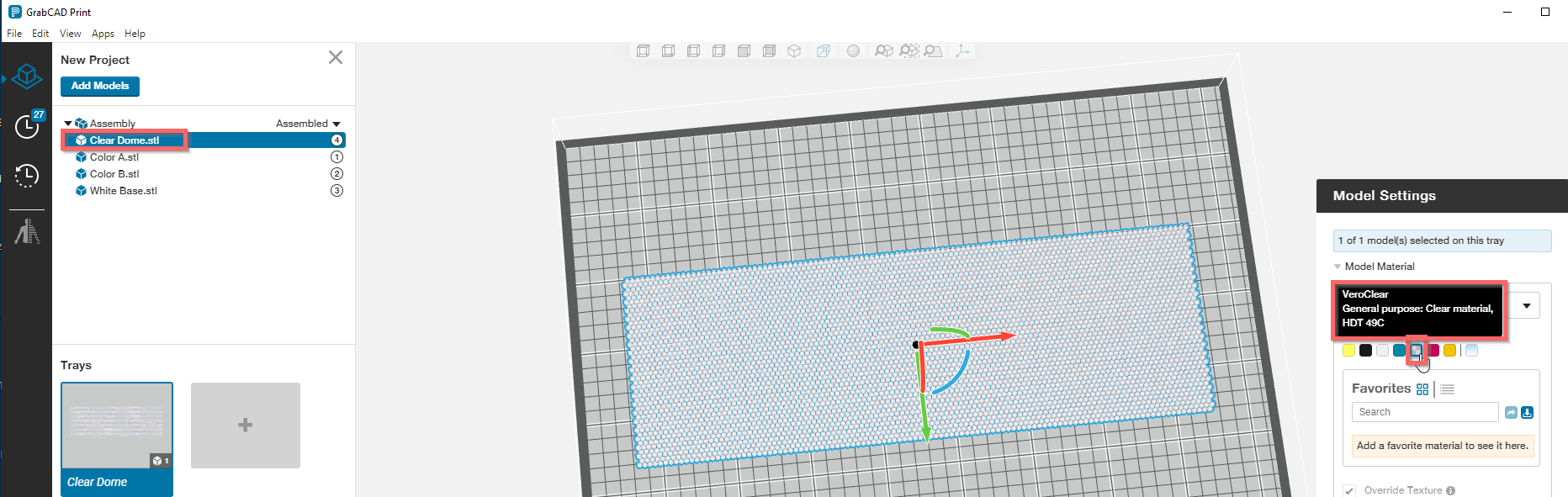
I made the following material Assignments
- Clear Dome =- Vero Clear
- Color A = Vero Magenta Vivid
- Color B - Vero Cyan Vivid
- White Base - Vero Ultra White
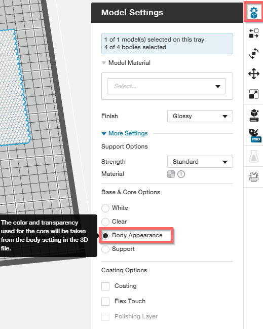
Foloowing this I selected all bodioes and ensured that the "Body appreance" option was selected
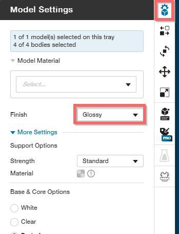
And make sure that all models are printed in "glossy" finish
Finally go to the 3D Fashion options plane and ensure that the Adhesion layer is selected

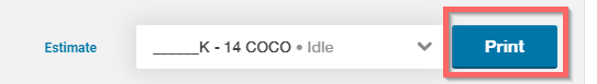
Now your ready yo send to print
-
Step 5: The Final Result
Model and print files can be found here
In the next tutorial we will loook at how to section this array into a different shape and apply two image textures to the array
