

Modeling a Clockwork Type Spring with Alibre Design

Alibre Design is a low cost 3D modeling and 2D drafting application that is functionally similar to Solid Works and Inventor, but at a fraction of the price. It does not come with surfacing tools, FEM, or animation, but if I had a requirement for these functions I can purchase them as ad-dons. As a small time, semi- retired CAD contractor if I purchased Solid Works or Inventor I would not make any return on my investment, I would need to be unethical and pirate these software's or be prepared to never make a profit but only a loss.
Alibre Design, for the most part is quite like using Solid Works or inventor but had a couple of features not found in these two applications. The method I use in this tutorial is one of these features.
-
Step 1:

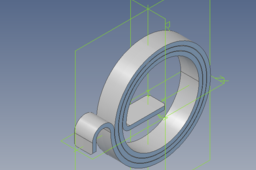
The finished spring

Flat pattern
-
Step 2:

The first step is to select a start plane on to which a sketch is made. From this sketch a sheet metal tab is created. In this case I have set the material parameters for a material that is 1 mm thick.
-
Step 3:

Once the initial sheet metal tab has been created, the function editor is opened. I have made a new function, I have named ADD ( highlighted ). I have set up an equation for this function : ADD : AD_Thickness+0.1. AD_Thickness is the system variable for the material thickness. This function takes the material thickness and adds 0.1 to this value. This is for pattern to flatten each coil must not interfere with other coils. This function will be used to create the coils for the spring
-
Step 4:

Next the first bend is made. The bend radius is left as the minimum bend radius as set up in the material properties for the design file. The angle for the bend is set to 90 deg and the " bend only " box is checked
-
Step 5:

The first spring coil is now created next. I have set the bend radius, in this case to 10mm and having checked the " bend only " box and the bend angle to 180 deg. I click " OK " to close this dialogue. I then open the function editor and note that the system has named this radius dimension variable " D18 ".
-
Step 6:

The next coil is made, but we now set the bend radius to be D18 + (ADD/2). This makes this coil just big enough to finish outside the previous coil. The system names this radius dimension D25.
-
Step 7:

Next coil now made the same way. Bend radius D25 + (ADD/2), with the dimension variable named D32.
-
Step 8:


This process is continued to produce the next 2 coils. The name the system gives to each radius dimension is used to create the next bend.
-
Step 9:

Repeat process until you have made the required number of coils
-
Step 10:

The last bend forms the hook on the end of the spring. In this case the bend radius is set to 2mm and the "bend only" box is unchecked and a length for the bend tab set.
