

Modelling welds with FreeCAD 0.19

This tutorial explain how to model welds with FreeCAD, version 0.19. For that we will use epsiloidal primitive sequences placed on the weld seams. Principle is described in Step 1 and then other steps describe practical cases. We will mainly use Part and Draft workbenches and functions Primitives, Epsiloid and Path Array.
-
Step 1: Principle of adding 3D welding graphics
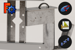
First, we need a part on which to do our welding. I'm going to use a part that I have modeled before but you can use one of your own parts. Here is a screenshot of the part choose, it's a nacelle for Piggot wind turbines (part that holds generator and hub of propeller).

Functionally there is no interest, it is only visual to be able to represent the welds in a realistic way. As close as possible to the real object, shown below.

It is not advisable to leave the welds on a 2D drawing as this overloads the whole thing for no good reason. That's why I make several versions of the same file with a version without welding.
The version without welding is used for the drawing:

The version with welding is used for the rendering :

There is no function to automatically add welds in FreeCAD. The goal will be to place primitives representing welds in order to obtain a result as close as possible to reality. Principle is to insert a succession of primitives along the weld seams :
• First we place a primitive...

• Secondly, it is reproduced along a path...

The result is weld seams as shown below, it's quite a time consuming job for large assemblies.

-
Step 2: Weld along an edge
2.1. Go to Part workbench,

2.2. Create a primitive object,

2.3. Choose an elipsoid with default parameters,

2.4. Right clik -> Transform : to bring it closer from the weld area and press OK,

NB : Primitivemust be in the same direction as the edge,

2.5. Go to Draft workbench,

2.6. Select elipsoid and edge,

2.8. Activate function Path Array,

2.9. Configure PathArray and Ellispoid objects to achieve the desired graphic appearance.


-
Step 3: Weld along a line
If you want the weld to stop before the end of the edge you can do the same with a line.
1.1. Go to Darft workbench,

1.2. Use Line function,

1.3. Draw a line,

1.4. Do the same as before except that you select the line instead of the edge.


-
Step 4: Repeat a weld seam
To avoid having to repeat the same operation several times you can copy and paste the previously created weld seams.

4.1. Select PathArray object then press Ctrl + C / Ctrl + V,

4.2. Move the PathArray copy,


-
Step 5: Welding layers
You can overlay primitives as below to get a weld layer look.


-
Step 6: Welding around cylinder
To weld around cylinders, simply select the circle at the base of the cylinder when applying the Path Array function.
6.1. Create epsiloid,

6.2. Select primitive and circle,

6.3. Apply Path Array function,

6.4. Configure the Path Array object.

-
Step 7: Welding around a circle
It is possible to make a Path Array along a circle to make a circular weld.
7.1. Draw a circle,

7.2. Select primitive and sketch,

7.3. Apply Path Array,

7.4. Configure Path Array.

-
Step 8: Export
If you display the hidden primitives.

You will see that the method has created some wild elipsoids that you should take care not to export to have a nice rendering.

So before exporting, select the items you want, without the elipsoids.

Then the export will be clean.

