

Sheet Metal Bend Allowance

This tutorial is a look at how bend allowances are calculated for sheet metal parts. We will only look at bend allowances as they apply to the type of sheet metal parts that we produce using the common sheet metal tools. Calculating bend allowances for this type of part is a simple process. Calculating the blank size for parts that are produced by stamping flat blanks in complex dies is a much more complex process that is outside of the scope of this tutorial.
I have produced a PDF version of this tutorial. If you want a copy of this PDF version you can send me a GrabCad message with an email address to send it to
-
Step 1:

This is the type of simple sheet metal part we will look into. The first step in modeling this type of sheet metal part is to set up the sheet metal parameters required.

As Alibre Design software is what I use, the image shows the the sheet metal parameter set up for this application. In this case, the part is to be made from 2mm thick mild steel sheet. I have set the minimum bend radius to be the same as the material thickness. I have found, for most sheet metal parts that I model, this is a suitable value to set this variable to, The other initial setting to take note of is the setting labeled K-Factor. To help us understand what this variable is for we will now look into the theory as regards to what happens to a piece of sheet metal when we bend it.

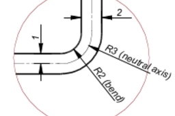
When we bend a piece of sheet metal, the metal at the outside of the bend is stretched and the metal at the inside of the bend is compressed. The line through the middle of the thickness of the sheet metal part is named the neutral axis. In a pure theoretical world this neutral axis is neither compressed or stretched, but stays the same length. In the real world though, this is not the case, as depending on the physical properties of the material this neutral axis will shift slightly inwards or outwards and therefore its length will change. The K-Factor is a factor is a factor we apply to compensate for this. Most CAD sheet metal applications seem to have a default value of 0.330 for the K-Factor. The exact settings you will use for any particular sheet metal part you are modeling is dependent upon the material your part is made from. For parts made from aluminum usually set the minimum bend radius to be 1½ to 2 times the material thickness, as depending on the grade and hardness of the aluminum being used, the aluminum will fracture at the outside of the bend.
 For sheet metal parts made from mild steel I usually set the K-Factor to 0.250 for parts that are being made by a skilled trades person using standard tooling, press brakes, guillotines and laser or turret punched parts. The reason I do this is to produce drawing sheets that reflect the method of manufacture. Using this sort of tooling a good crafts person can be expected to efficiently work to a tolerance of around 0.5mm. If you give these crafts person drawings with dimensions to 1/10ths or 1/100ths of a millimeter, they will see you as a bit of a beginner. The exact value you will use for the K-Factor will depend on the material you are using, the method of manufacture, consistency of the material you are using, and the required tolerance of the finished parts. When you are looking at large production runs with automated tooling, setting the exact dimensions for the blank will be after a few test parts have been run. Consistent material is an important factor in producing consistent parts. If, for example, you are required to produce a large quantity of parts from 3mm thick mild steel difficulties can arise from where the material was sourced from. The material that arrives from different countries of origin may be purchased as 3mm thick may be 3mm, if made in country that uses metric standards, sourced from a country that uses imperial units, this could actually be 1/8th inch, actually 3.175mm or even 10 gauge, which is about 3.6mm or 11 gauge which is close to 1/8th inch. The part model can be adjusted to work with the material that is delivered to you. Sometimes due to what material is available locally, a mix of this material from different sources will arrive and due to the difference in the material, all purchased as 3mm mild steel, it will be difficult to produce consistent finished parts.
 -
Step 2:

We will now look at how we manually worked out the required size for our blank part before we had the wonderful tool of 3D modeled parts. Returning to the detail of the bend we can see that the neutral axis, the part that theoretically stays the same length, is ¼ of a circle, so we can calculate the developed length of this ¼ circle by :

 From the drawing of the elevation of our part we can now work out the theoretical length of the neutral axis, the length of our part blank.
This gives us length of blank = (straight part of flange x 2) + (bend x 2) + (straight part of base)
 = 32 + 9.424 + 192 = 233.424 This does not make any allowance for distortion of the neutral axis. Some old engineering books have tables of factors to be applied to this calculated length. A crafts person working on the shop floor, making a few parts, using basic tools would use the following method to make this part using the following quick approximation method :
minus 2 x material thickness from the outside length of the part = 200 – 4 = 196, one material thickness for each bend, the for each flange over all height, minus 1 x material thickness
= 20 – 2 = 18 then adding it all up to calculate approximate blank length we get :
18 + 196 + 18 = 232 which for only a few parts, a hand drawn sketch, a competent crafts person and the finished part will be made and ready for the customer faster than you can produce a model and flat pattern with your CAD tools
-
Step 3:
Now we will compare the results we have obtained manually with both the full calculation and the approximate method with what we get with a proper 3D model and the drawing produced from this model.
 Part drawing produced from modeled part
Flat pattern generated from modeled part
For this modeled sheet metal part I set the K-Factor to 0.250 with the dimensions set to o decimal places I get a dimension for blank length of 232mm, the same as I get for the approximate method. With this set to 2 decimal places it comes out as 231.85mm. This is the reason I set K-Factor to 0.250. If I set K-Factor to 0.330 this comes out as 232.36mm.
The exact value of the K-Factor we use will effect the finished size of our blank part but consideration must be given to the tolerance and accuracy required by the finished component and the method of manufacture and how much effort it is worth putting into setting this value. The finished part must be good enough to perform as designed but there is no advantage in making it better then it needs to be. This just makes it cost more than it should be.
