

Staggered pulley modeling in AutoCAD and rendering.

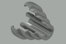
- Staggered pulley modeling in AutoCAD and rendering.
- Modelagem de polia escalonada no AutoCAD e renderização.
- Modelado de poleas escalonadas en AutoCAD y renderizado.
-
Step 1: Dimensions of the stepped pulley
- The stepped pulley will have the dimensions of the figure below:
- A polia escalonada terá as dimensões da figura abaixo:
- La polea escalonada tendrá las dimensiones de la figura abajo:

-
Step 2: Profile for the REVOLVE command
- Draw the following profile in the top view.
- Desenhe o seguinte perfil, na vista superior.
- Dibuje el perfil siguiente en la vista superior.

-
Step 3: Adding rounded end
- Make a circle with a radius of 144 units.
- Faça um círculo com raio de 144 unidades.
- Haga un círculo con un radio de 144 unidades.

- Draw a line in the upper quadrant with a length of 35 units.
- Trace uma linha no quadrante superior com comprimento de 35 unidades.
- Trace una línea en el cuadrante superior con una longitud de 35 unidades.

- From the end, draw a line of any length. From across the circle.
- A partir da extremidade, trace uma linha de comprimento qualquer. Desde atravesse o círculo.
- Desde el extremo, trace una línea de longitud cualquiera. Desde atravesar el círculo.

- Delete the excess line using the TRIM command.
- Apague o excesso de linha usando o comando TRIM.
- Borre el exceso de línea usando el comando TRIM.

- Position the horizontal line at the bottom of the vertical line with the MOVE command.
- Posicione a linha horizontal, na base da linha vertical com o comando MOVE.
- Coloque la línea horizontal en la base de la línea vertical con el comando MOVE.

- Delete the rest of the circle with TRIM command (TRIM + ENTER + ENTER / click on the follow-up to be deleted).
- Apague o restante do círculo com comando TRIM (TRIM+ENTER+ENTER / clicar no seguimento que se quer apagar).
- Borrar el resto del círculo con el comando TRIM (TRIM + ENTER + ENTER / hacer clic en el seguimiento que se quiere borrar).

- Move the arc through the end and position it on the profile of the stepped pulley. Remove the horizontal lines from the top.
- Mova o arco pela extremidade e posicione sobre o perfil da polia escalonada. Remova as linhas horizontais da parte superior.
- Mueva el arco por el extremo y coloque sobre el perfil de la polea escalonada. Quite las líneas horizontales de la parte superior.

- Using the FILLET command, round the inner edges (FILLET / RADIUS / "VALUE").
- Usando o comando FILLET, arredondar os cantos internos (FILLET / RADIUS / "VALOR").
- Utilizando el comando FILLET, redondear las esquinas internas (FILLET / RADIUS / "VALOR").

- Make a parallel copy of the lower end line using the OFFSET command.
- Faça uma cópia paralela da linha da extremidade inferior usando o comando OFFSET.
- Haga una copia paralela de la línea del extremo inferior usando el comando OFFSET.

- Use the REGION command in the profile.
- Use o comando REGION no perfil.
- Utilice el comando REGION en el perfil.

- Change the view mode from TOP to SE ISOMETRIC.
- Altere o modo vista de TOP para SE ISOMETRIC.
- Cambie el modo de vista de TOP a SE ISOMETRIC.

-
Step 4: Apply comado REVOLVE
- Use the REVOLVE command on the surface. The axis of rotation is the line at the side of the surface. Click first on point 1 and then point 2. Enter the angle value of 270 (or another value, less than 360).
- Use o comando REVOLVE na superfície. O eixo de rotação é a linha ao lado da supefície. Clique primeiro no ponto 1 e depois no ponto 2.Entre com o valor do ângulo de 270 (ou outro valor, menor que 360).
- Utilice el comando REVOLVE en la superficie. El eje de rotación es la línea al lado de la superficie. Haga clic primero en el punto 1 y luego en el punto 2. Entre el valor del ángulo de 270 (u otro valor, inferior a 360).

-
Step 5: Selecting material to render.
- Click MATERIALS BROWSER on the VIEW tab.
- Clique em MATERIALS BROWSER, na guia VISUALIZE.
- Haga clic en MATERIAL BROWSER en la ficha VISUALIZE.

- Select the modeled part and choose the material inside "Autodesk Library" and click "adds material to document".
- Selecione a peça modelada e escolha o material dentro "Autodesk Library" e clique em "adds material to document".
- Seleccione la pieza modelada y elija el material dentro de "Autodesk Library" y haga clic en "adds material to documento".

-
Step 6: Render the patterned part
- Click "RENDER ENVIRONMENT AND EXPOSURE" in the RENDER sub-panel.
- Clique em "RENDER ENVIRONMENT AND EXPOSURE" no sub painel RENDER.
- Haga clic en "RENDER ENVIRONMENT AND EXPOSURE" en el sub panel RENDER.

- Click ENVIRONMENT so that it is "ON".
- Clique em ENVIRONMENT para que fique "ON".
- Haga clic en ENVIRONMENT para que quede "ON".

- Click on the RENDER TO SIZE sub-panel and select the dimension of the image.
- Clique no sub painel de RENDER TO SIZE e selecione a dimensão da imagem.
- Haga clic en el sub panel de RENDER TO SIZE y seleccione la dimensión de la imagen.

- Now that everything is set up, just click RENDER TO SIZE to render.
- Agora que tudo esta configurando, basta clicar em RENDER TO SIZE para renderizar.
- Ahora que todo está configurando, basta con hacer clic en RENDER TO SIZE para renderizar.

- To save, just click the DISK in the upper left corner or press ESC to cancel. The space that the image will occupy in the selected dimension, depends on the way it is being viewed. Thus, the larger the image, the larger the rendered image. The adjustment is made through the ZOOM in the AutoCAD workspace. It is possible to change the material and render again.
- Para salvar, basta clicar no DISQUETE no canto superior esquerdo ou apertar ESC para cancelar. O espaço que a imagem irá ocupar na dimensão selecionada, depende da forma que ela esta sendo vizualizada. Assim, quanto maior a imagem, maior a imagem renderizada. A ajustagem e feita através do ZOOM na área de trabalho do AutoCAD. E possivel alterar o material e renderizar novamente.
- Para guardar, simplemente haga clic en el DISQUETE en la esquina superior izquierda o pulse ESC para cancelar. El espacio que la imagen ocupará en la dimensión seleccionada, depende de la forma en que está siendo visualizada. Así, cuanto mayor sea la imagen, mayor será la imagen renderizada. El ajuste se realiza a través de ZOOM en el escritorio de AutoCAD. Es posible cambiar el material y volver a renderizar.


