

Tolerances in DIN 5480 splines

In this tutorial, I will address some topics regarding the flank tolerances in the standard DIN 5480 splines.
For an Asking of erick mireles about the meaning of 8f in an expression like
DIN 5480 W 120 x 3 x 38 x 8f
-
Step 1: Why involute profile is used in DIN 5480 and other standards?
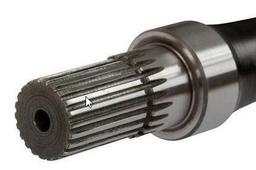
The reason for the involute profile is the fact that most external splines are manufactured in the way that you can see in this video. That is fast and delivers good accuracy results.
The involute profile is the same one used in Spur Gears (but not only in them). the reason is to get two profiles (involutes) that spin without slipping.
-
Step 2: Another manufacturing process
- Broaching.
- Rolling
- Milling
and so on.
-
Step 3: Centering the shaft and hub
Splines are machine elements that connect a shaft with a rotor. Next to transmitting torque, the spline might also be utilized to center the rotor to the shaft.
The tolerance system for spline joints is a system of deviations related to the theoretical values of zero clearance mating of the hub space width and shaft tooth thickness, which defines the permitted limits of flank clearance.

Clearances between the major diameter of the shaft spline and the minor diameter of the hub spline may be used for centering (diameter centering).

But It isn't the case for DIN 5480. The DIN 5480 series of standards applies to flank-centered fitted (side fit) splined connections. The flanks of the teeth are used both for transmitting the torque and for centering the hub and shaft relative to one another.
The diameters of the tip and root circles of the shaft differ from the respective diameters of the hub by at least the bottom clearance c.

-
Step 4: Actual vs. Effective Involute
The effective fit concept is based on the fact that a manufacturer simply can’t produce a perfect spline.
- The two splines must be coaxial. The possible interference issues are concentricity and runout.

- The tooth must not have a form error that would cause any portion of the tooth surface to be increased over the space size.

- The tooth size on the external part must be less than that of the corresponding space size of the internal mating part. The possible interference issues are tooth thickness and circular space width.

- The tooth/space must be in the correct angular position. The possible interference issue involves the index.

Actual Tooth Thickness is the circular thickness on the pitch circle of any single tooth, considering an infinitely thin increment of axial spline length.

ffective Tooth Thickness of an external spline is equal to the circular space width on the pitch circle of an imaginary perfect internal spline, which would fit the external spline without looseness or interference, considering the engagement of the entire axial length of the spline (i.e. the smallest space width that would contain the entire full length of the given tooth).

The same considerations are for tooth spacing.
- The two splines must be coaxial. The possible interference issues are concentricity and runout.
-
Step 5: Nomenclature
The permitted limits of the actual profiles of the hub and shaft are defined by space width and tooth thickness deviations. The associated tolerance zones are designated
by figures and letter symbols, the tolerance grade being represented by figures, and the tolerance position by letters.
Upper-case letter symbols are used to denote space width tolerances, and lower-case letter symbols denote tooth thickness tolerances.
Example: DIN 5480 W 120 x 3 x 38 x 8f
W – stands for “Welle” and denotes a Shaft/External spline
N – stands for “Nabe” and denotes a Hub/Internal spline
120 is the “Reference Diameter”
What is a “Reference Diameter”? Unlike ANSI B92.1 splines DIN 5480 was structured to “permit easy slip-fitting of components such as, for instance, ball or roller bearings… this condition is met by making the reference diameter equal to the bore of the bearing and then modifying the profiles of the teeth of the hub and the shaft accordingly.
The Reference diameter is not the Major or Minor diameter of the spline.
3 is the Module of the spline (size of the tooth)
38 is the Number of Teeth in the spline
8f is the Class of Fit
The number (8) represents the “Tolerance Class” of the spline. These range from 5 to 12.
Lower numbers have a smaller or tighter tolerance range.
-
Step 6: Tolerances Classes
The general tolerances are divided into classes.
The following factors must be weighed up during the design and construction process:
- The required accuracy of fit
- Costs. The tolerance class also determines how complex the production or procurement of the component will be. In all cases, the lower the tolerance, the higher the costs will be.
Going back to the previous example DIN 5480 W 120 x 3 x 38 x 8f

Tooth thickness 6.271 mm

T : dimensional tolerance
TE : individual tolerance (for individual measurement)
s : shaft tooth thickness
N : basic dimension, Tooth thickness 6.271 mm
Gs = N + Ase
GsE = N + AseE
Get the values from Table 2 DIN 5480 -14

Ase = -28 AseE = -51
Gs = N + Ase = 6.271 m - 0.028 mm = 6.243 mm
GsE = N + AseE = 6.271 mm - 0.051 mm = 6. 22 mm
