

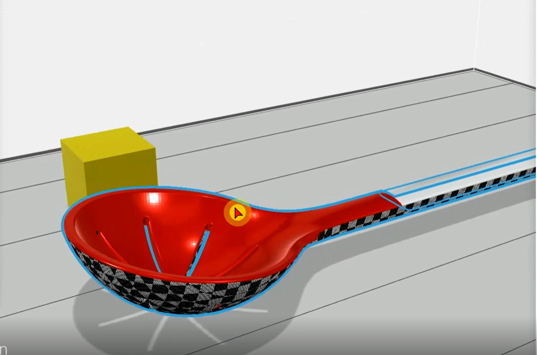
Transparent 3D Printing is Easy with GrabCAD Print

The visualization tools in GrabCAD Print make clear 3D printing easy! There are a number of ways to apply transparency to your part, and then view which areas will have a matte or glossy finish. This is really helpful so you can change the orientation of the part to suit your needs.
-
Step 1: Check Your GrabCAD Print Version
This tutorial will teach you how to navigate the new GrabCAD Print Polyjet UI so that you can apply transparency to your part, and choose whether or not the surface is glossy or matte.
This first video is applicable to GrabCAD Print version 1.39 and above. If you have a previous version, skip to Step 6.
-
Step 2: Make Sure VeroClear or VeroUltraClear is Loaded
VeroClear/UltraClear is a transparent 3D printing material that closely mimics PMMA (acrylic). It is a great alternative to actual glass because of its rigidity and relative flexibility. Due to the material also being colorless, it can also blend with other Vero/VeroVivid colors.
Please be sure to check your printer’s loaded materials so that you can print your transparent part!
Another way to find your loaded materials is by looking at your Model Settings and looking at the drop down menu and selecting Tray Materials.
-
Step 3: Add Transparency
The easiest way to add transparency in GrabCAD Print is to use the slider. It can be found under Model Settings along with the Color Picker. As you manipulate the transparency slider, the ratio of VeroClear and the Vero color of your choice will change.
This can also be achieved by selecting Vero Clear or Vero UltraClear when you are within the tray material menu for complete transparency.
The more transparent the part, the more VeroClear is being used. You can add transparency to a specific body or to the part as a whole.
IMPORTANT NOTE: Pure VeroClear parts will turn yellow if overly exposed to the UV lamp which cures the material. If you have a large/tall part with many smaller parts that are present, keep the large/tall part far away from the smaller parts so that they do not receive too much UV exposure.
Printing the tall part separately will solve the problem as well.
-
Step 4: Check Support Visualization
Once you have the transparency of your choosing, it is very important to know where support material will touch your part especially if it is transparent! Sections of your print that have support material will make them matte instead of glossy.
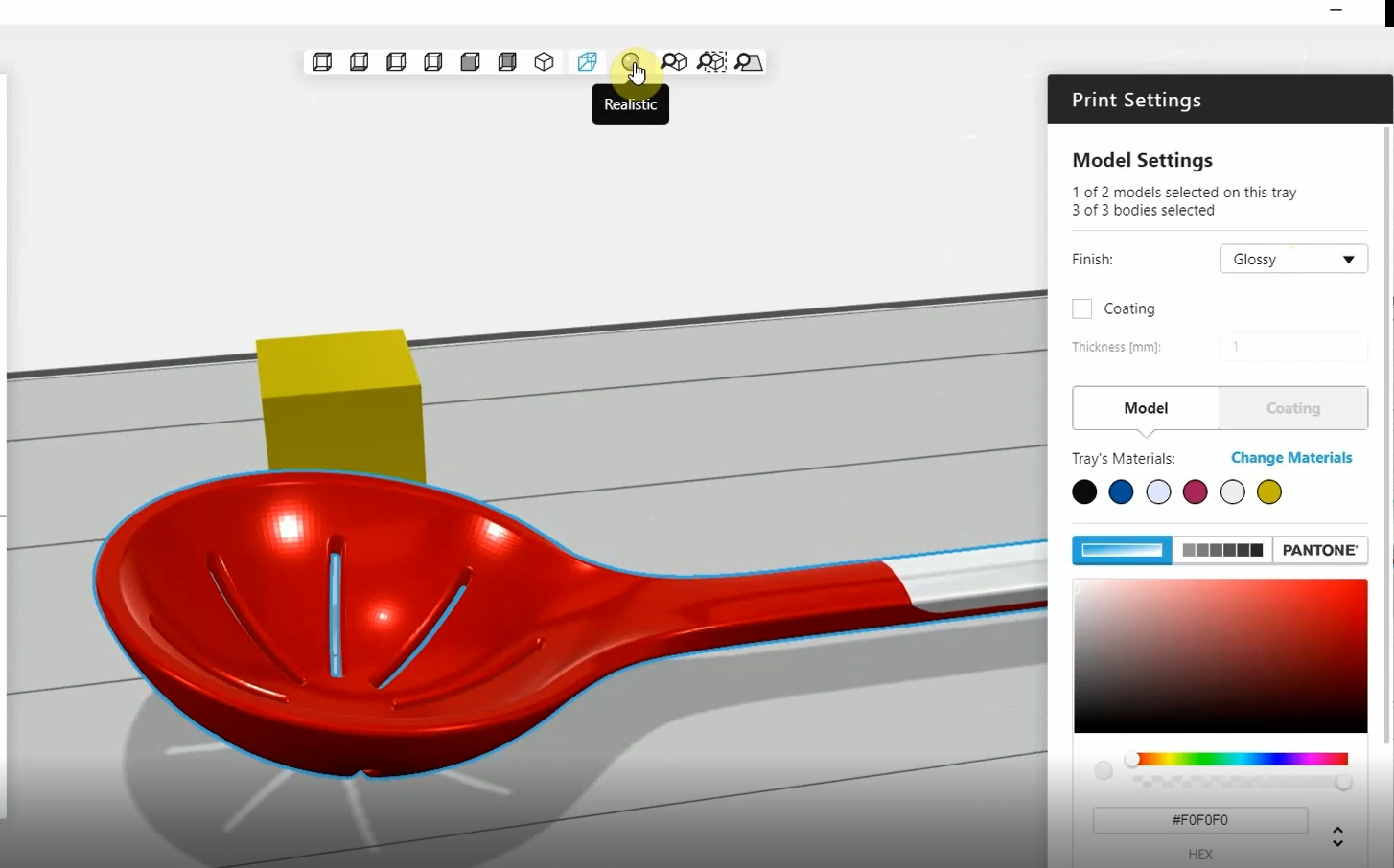
You can figure out what will end up matte or glossy by clicking on Preview Supported Surfaces. This will show you a binary view of the part.
The checkerboard pattern indicates where support material will be present.
If you have a part that has many faces like a gem or taillight, it is important to orient the part so that it is support material free. This prevents you from wasting unnecessary amounts of time post-processing which could also ruin your part!
-
Step 5: Transparent 3D Printing
For more transparency tips for clear 3D printing, check out these GrabCAD Tutorials:
-
Step 6: Applying transparency in GrabCAD Print 1.38 and previous versions
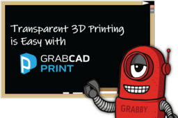
To add transparency in GrabCAD Print 1.38 version and earlier, select the area of the part you want to make transparent.
- Click Print Settings
- Click the color slider at the bottom
Adjust the slider and move it to your desired transparency. As you move it, you'll notice the part becoming more transparent.
Another way to add transparency is by simply inputting the Hex value into the code fields below the slider.
Once you've selected your desired transparency, it's important to check where the support material will touch your part-- because remember, this will affect whether it has a matte or glossy finish.
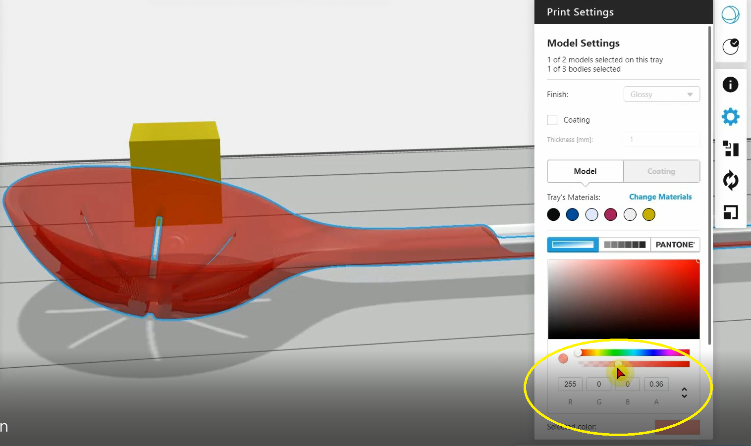
As you rotate the preview image, you can clearly see which areas are glossy and which are matte. However, if you want to double check this, click the Realistic ball icon at the top of the menu.
The Realistic view gives you a binary view of the part. The hatching is indicative of where the support is going to be touching your part.
If you're not OK with where the support material touches your part, change your part orientation to get the surface finish you want.


