

Tutorial: how to model soap bar in autodesk Inventor 2013

Here is the Tutorial :)
-
Step 1:
Open Autodesk Inventor , Create New part (mm), and Create sketch,
like in this picture below.
-
Step 2:
Select work Plane to become the base of the sketch.

-
Step 3:
Draw an Arc Look Like the Picture, let call this is Sketch 9

-
Step 4:
After that , Click Finish Sketch. on the right top corner of the Inventor.

-
Step 5:
Draw Sketch Again , in the other Work plane that perpendicular with the previous one. Project Geometry on the corner point of the sketch, then draw some arc look like the picture start and end in the projected geometry corner point. lets call this is sketch 10.

-
Step 6:
after finish it should be look like this.

-
Step 7:
then draw sketch again, mirrored/opposed from sketch 10. you can redraw it, or use mirror feature. lets call it sketch 12

-
Step 8:
Create new work plane.

-
Step 9:
then click on the our reference work plane then drag into the center of our object (-50 mm)

-
Step 10:
create new sketch on the new work plane, then create project geometry from point 1, point 2 and point 3, then draw an Arc base on point 1, point 2, and point 3, let call it sketch 13.

-
Step 11:
Create loft feature.

-
Step 12:
for the section, we select sketch 12, sketch 9, and then sketch 10, (it can be opposite). and for the rail we choose sketch 13(the only sketch that perpendicular with other sketch), just look like the picture. then Click OK.

-
Step 13:
then the result should be look like this.

-
Step 14:
Right Click on the unnecessary object(sketch, work plane, etc), and unchecked the visibility.

-
Step 15:
then it should be look like this.

-
Step 16:
create another sketch on the bottom of our object, just like sketch 10 or sketch 12, you can redraw it, or using project geometry, or just right click on the sketch 10 or 12, then check share sketch, to make it reusable again, lets call it sketch 17.

-
Step 17:
create the other side (opposite/mirrored), lets call it sketch 18.

-
Step 18:
create a work point, and work plane(or you can use the previous one).
like this in the picture bellow.
-
Step 19:
create new sketch on the work plane, and create a project geometry from the work point, and draw a sketch look like this picture bellow. finish sketch.
lets call this sketch 20.
-
Step 20:
create new work plane and work point same as in the picture bellow.

-
Step 21:
then create new sketch on the new work plane. and create a project geometry from the work point, and draw a sketch look like these picture bellow. finish sketch.
lets call this sketch 21.
-
Step 22:
create loft feature, for the section, select sketch 18, then sketch 21, then sketch 17. and for the rail, we select sketch 20, just look like the picture bellow. and click OK.

-
Step 23:
the result it should be look like this picture bellow

-
Step 24:
create a sculpt to convert this object from surface in to solid object.

-
Step 25:
Just Click Two Surface (loft) that we create earlier and Click Ok...
See This picture bellow.
-
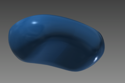
Step 26:
the result, should be look like this. (in this picture I change the color in to Cyan, the Default color is look like grey)

-
Step 27:
Create a new work plane, 20 mm from the center of Object.

-
Step 28:
create new sketch on the new work plane, and draw two Ellipse like this picture bellow.

-
Step 29:
Create an Extrude Feature

-
Step 30:
Select our previous Sketch, and setting extrude mode same as this picture bellow.

-
Step 31:
the result should be look like this.

-
Step 32:
create new work plane.

-
Step 33:
create split feature.

-
Step 34:
select the new work plane as the split tool. and setting the split feature like this picture bellow, then Click OK.

-
Step 35:
the result should be look like this picture.

-
Step 36:
create new sketch on the previous work plane, and create a Text.

-
Step 37:
just write as you like, in this example i write "SOAP", don't forget to setting it's height, font type, location, etc.

-
Step 38:
the result should be look like this picture.

-
Step 39:
create a emboss feature.

-
Step 40:
select our text as the profile, and the est setting just look at this picture bellow.

-
Step 41:
Then Our Soap Bar is Done :)

-
Step 42:
This is Top View, with realistic view setting :)

-
Step 43:
This is Bottom View, with realistic view setting :)

-
Step 44:
I Hope this Tutorial is Useful for every one who need it :D
Thank You....
