

Tutorials on Injection Mould Designing

Hello Guys, Today i gonna give you details about Runner less Mould.
-
Step 1:
Any mould in which a conventional runner system is not incorporated is called a runnerless mould. A mould which incorporates a direct feed from the nozzle is a basic runnerless mould.
This basic arrangement have been developed in order either to reduce the sprue length or to eliminate the sprue altogether by using different types of nozzle designs.
There are four types of nozzles.
Long reach nozzle
Barb nozzle
Antechamber design
Multi-nozzle manifold1. LONG REACH NOZZLE : These extended nozzles protrudes into a packet machined in the mould plate thus reducing the length of sprue gate. The temperature of the nozzle is controlled by heating it by using a resistance type of band heater or a thermo-couple.

-
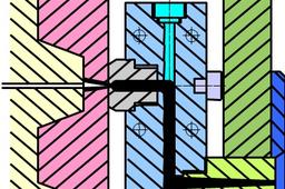
Step 2:
2. BARB NOZZLE
To reduce the blemish being left at the injection paint due to a conventional sprue gate, the barb nozzles are used. A reverse tapered sprue and a pin gate arrangement is possible by using a barb or Italian nozzle. The projection of the end of the nozzle incorporates barbs and is accommodated in the reverse tapered sprue.

-
Step 3:
3. ANTECHAMBER DESIGN
This is also known as the hot well design. A small mass of material is retained in the antechamber. The plastic material adjacent to the mould partially insulates the central core of plastic material from the cold mould allowing it to pass through the antechamber into the impression. As it is not necessary to remove the sprue from the mould, fast moulding cycles can be achieved.

-
Step 4:
4. MULTI-NOZZLE MANIFOLD
Multi-nozzle manifold is used for direct feeding of material for multi impression moulds. It consists of a manifold block suitably drilled to provide a flow path for the material, into which the required number of nozzles are fitted.

-
Step 5:
HOT RUNNER MOULDS
The location of the impressions is not confined to the control region of the mould. Therefore a large number of widely displaced impressions can be fed at the same time.
The mould is not restricted to a particular machine
It allows for pin gating of mouldings on multi-impression moulds.
It allows for multi-point pin gating on single-impression and multi-impression moulds
It allows for side or film gating of large mouldings.
-
Step 6:
VALVE-GATED HOT-RUNNER UNITS
In this design of hot runner unit, valves are incorporated within the unit to seal off the gates for particular period of moulding cycle. A needle valve is actuated, when required, by a hydraulic cylinder via a lever arm. In the forward position the front end of the needle valve seals against a complementary tapered orifice within the secondary nozzle, thereby preventing material flow through the gate.
-
Step 7:
INSULATED RUNNER SYSTEM
This system is based on the principle that plastic can be used within the mould as an insulation medium because of their low thermal conductivity. This design is a modification of the underfeed type, the difference being that larger runners are incorporated and a latch arrangement is included to keep the feed plate and floating cavity plates locked together.
The plastics material forms an insulating skin of frozen material adjacent to the runner wall (metal) while the central core remains in the molten state. Larger than normal runners are necessary to allow for this insulating skin and the diameter of the runner should not be less than 12mm. Quick release latches are necessary to permit the runner to be removed from between the feed and floating cavity plates, in case the runner become solid due to inconsistent conditions.
