

Wireframe and Surface Design and Part Design of a mouse

In this tutorial I am going to teach the basic steps of designing a mouse using Catia v5R21.
-
Step 1: Go to start > Mechanical Design > Wireframe and Surface Design
-
Step 2: Sketch a rectangle of 100mm by 50mm and give its edges a curved radius of 20mm

-
Step 3: Use plane definition and choose plane type as “Offset from plane” from the ZX axis with an offset distance of 22mm

-
Step 4: Choose the plane created in Step 3 and sketch an arc of a circle with a radius of 85mm

-
Step 5: Use the same method used in step 3 to create another plane, then just click on the “reverse direction” icon.

-
Step 6: Use the projection tool to create a same arc of the circle but on the newly created plane

-
Step 7: Create another plane. But this time the plane type is “Normal to curve”. Therefore, you select the curve create in step 4 and click on its endpoint as the edge

-
Step 8: Click on the newly created plane and sketch a line as shown below.

-
Step 9: Use corner definition to trim the unwanted lines. Choose corner type as “3D Corner”.

-
Step 10: The same method used in step 9

-
Step 11: Use the split definition tool to trim the unwanted lines as shown below

-
Step 12: Create another plane that is normal the curve as shown below

-
Step 13: Sketch a line and coincide its points as shown below

-
Step 14: Use corner definition as used in steps 9 & 10.

-
Step 15: Same method as used in step 14

-
Step 16: Use split definition as used in step 11

-
Step 17: Use the Fill definition to create a sheet by choosing the bottom side as the guiding edge as shown below

-
Step 18: Use Fill tool and select all the boundaries as shown and apply it.

-
Step 19: Give boundary definition

-
Step 20: Give boundary definition

-
Step 21: Use multi-section surface definition to cover up the remaining open parts

-
Step 22: Go to start > Mechanical Design > Part Design

-
Step 23: Give thickness of 1mm to each surface

-
Step 24: Give an edge fillet of 0.54mm

-
Step 25: Edge fillet of 1mm from the bottom side

-
Step 26: Choose the XY plane and sketch diagrams as shown below

-
Step 27: Use pocket definition and create a pocket of 27mm and reverse its direction

-
Step 28: Start > Mechanical Design > Wireframe and Surface Design

-
Step 29: Use Fill definition and fill the games created in the previous step

-
Step 30: Choose the ZX plane and sketch a circle of D22

-
Step 31: Apply the pad definition and tick the mirrored extent icon as shown below

-
Step 32: The same method in step 31

-
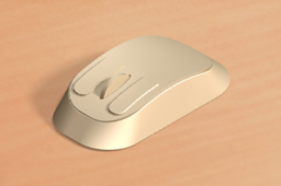
Step 33: Hide all the sketches and planes. The final product is a mouse

-
Step 34: Rendering the body designed in step 33

