

Learn about the GrabCAD Platform
Get to know GrabCAD as an open software platform for Additive Manufacturing
Visit our new homepage
Show off your skills and solve real design problems

Technical Background:
In space, there's a growing need to build large, precise structures like antennas, booms, and telescopes. These structures are too big to fit inside a rocket during launch, so we need a way to deploy them once they reach their orbit.
One idea for deployment is the Starburst architecture, which uses high-strain rods to deploy and cables to pull the different parts after launch. While the cable could hold them together by itself, the cable may lose tension over time. Also, a tensioned cable can impact deployment accuracy. That is where you come in! Your challenge is to create a mechanism that can securely lock these parts in place when they come together. However, there's a tricky part – during the intense shaking of the launch, we must make sure the mechanism doesn't accidentally trigger. It should only activate when the intended components come together and are properly aligned.
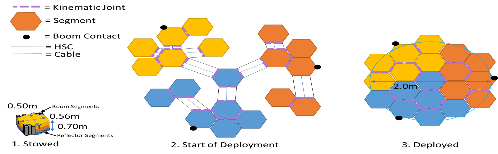
Our key example is an Earth-observing antenna. The antenna's segments are stacked neatly on top of each other, taking up a compact space (1). After launch, the segments are released from their locked positions, and a set of high-strain rods deploy the system into an initial configuration (2). Each element is aligned correctly by two high-strain rods, so they can be pulled together. Once the antenna opens up, the cables start retracting, gradually pulling in each segment until they form the final deployed shape (3). The segments are precisely located relative to each other using special joints, with an accuracy of around 20 microns, and held in place by the tension in the cables. The overall surface alignment has a root mean squared (RMS) error of approximately 60 microns. Check out the image below for a visual representation of how the antenna transforms from a packed state to a fully deployed state. Your challenge is to come up with a mechanism that locks the segments together when they come together in the deployed state (Image 3). Can you design a mechanism that ensures secure latching on contact, but will not accidentally latch during launch?
Ground Rules:
The study "Starburst: A Revolutionary Under-Constrained Adaptable Deployable Structure Architecture" demonstrated a unique approach to deploying large antennas to much higher accuracies than ever before. Currently, the segments are held together with cables, which can apply a limited amount of force and may lose tension over time. Accuracies can be improved with stronger connections between the deployable segments that will lock in place with the segments touching each other.
The goal is to design a mechanism, which when two segments come together, will lock them together with an adjustable amount of force, between 50 to 200 Newtons. It can be assumed that another system brings the two segments together and aligns them to within 1mm or better. This system just needs to latch them in place to each other on contact. The system must operate independently when the segments come together, and not require any wires or other transmission lines connected to the primary spacecraft. The image shown below illustrates how the two segments contact each other. At the edge of the hexagons are plates perpendicular to the plane of the hexagon. The plate forms the kinematic contact. The blue hexagon and plate in the image below connect to the gray hexagon and plate.
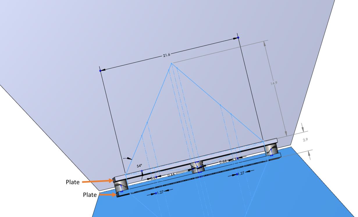
The mechanism should fit in the volume illustrated above, with each side of the latching mechanism fitting in an isosceles triangle extending from the plate that is 20.6cm (8.5”) wide by 14.9cm (5.9”) tall, with an out of plane depth of 5 cm (2”). This includes the latch and any actuators, springs, or power storage systems to actuate the latch. It also must not interfere with cylinders running through the triangle. During operation, the latching mechanism is allowed to expand beyond the 5cm depth constraint.
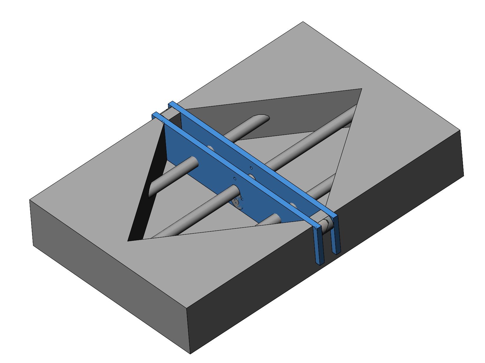
The latching mechanism must attach to the segments by the two plates which are spaced apart by 2.9cm (1.15”). To explain the physical constraints, a model of the negative space the latching mechanism is allowed to fill is provided. There are two models, one with just the negative space, and a second with the negative space and the plates. Holes and other features can be cut in the plates at any location (except for the regions of the keep-out cylinders) to accommodate the latching mechanism. However, the latch must fit in the negative space volume without interfering with any of the cylinders running through the negative space.
Both sides of the latching mechanism combined should weigh less than 1 kg (2.2lbs). It must work in the vacuum of space, and a variety of temperatures. The mechanism must be able to be triggered at any temperature between -10C to 60 C (14F to 140F) and survive temperatures ranging between -60C to 100C (-76F to 212F).
The system cannot be triggered without the latching components coming together. For example, high G-forces or shock loads that come with spacecraft launch should not trigger the mechanism. Expect that the mechanism could see accelerations up to 250 G’s. Finally, the system cannot use magnets, as these have the potential to impart large torques to the spacecraft, given they are on a long structure within Earth's magnetic field.
Bonus Challenge: It can be helpful to have impacts after latching help settle the kinematic mount. If your latch can create 3 small shock loads of 9 N (2 lbs) each after latching, spaced at least ¼ of a second apart, this can help improve the accuracy of the kinematic mount.
Assumptions:
Assumptions are initial starting points surrounding the project. These may be changed if justifying rationale emerges as the project develops.
Graphical Products
Data Product
JUDGING Factors
1. Low mass with ability to generate a large load.
2. Meets physical constraints
3. Resistance to unintentional activation
4. Feasibility of manufacturing and fabrication
5. Quality and fidelity of the 3D models
6. Validity and soundness of structural analysis
7. Completing the bonus challenge, creating 3 impact loads after latching.
Requirements needed for Submission
Model File Formats shall be delivered in STEP or IGES.
Renderings: Two separate viewing angles and a packaged/Pre-deployed view (.jpg or .png formats)
Any supplemental description and structural analysis documents shall be in PDF format
If zipped, the file compression shall be compatible with Windows 10 and not require any special software to unzip.
Eligibility
Solutions from countries listed as Type 1, 2, or 3 on the NASA Designated Countries List are Not eligible for prizes.
Intellectual Property
The Government is seeking a full government-purpose usage license for the further development of a heavy logistics Transport concept. It is hoped that the winning concepts can be included in the follow-on study.
ENTERING THE COMPETITION The Challenge is open to everyone except employees and families of GrabCAD and the Sponsor. Multiple entries are welcome. Team entries are welcome. By entering the Challenge you: 1. Accept the official GrabCAD Challenges Terms & Conditions. 2. Agree to be bound by the decisions of the judges (Jury). 3. Warrant that you are eligible to participate. 4. Warrant that the submission is your original work. 5. Warrant, to the best of your knowledge, your work is not, and has not been in production or otherwise previously published or exhibited. 6. Warrant neither the work nor its use infringes the intellectual property rights (whether a patent, utility model, functional design right, aesthetic design right, trademark, copyright or any other intellectual property right) of any other person. 7. Warrant participation shall not constitute employment, assignment or offer of employment or assignment. 8. Are not entitled to any compensation or reimbursement for any costs. 9. Agree the Sponsor and GrabCAD have the right to promote all entries. If you think an entry may infringe on existing copyrighted materials, please email challenges@grabcad.com.
SUBMITTING AN ENTRY Only entries uploaded to GrabCAD through the "Submit entry" button on this Challenge page will be considered an entry. Only public entries are eligible. We encourage teams to use GrabCAD Workbench for developing their entries. Entries are automatically given the tag "NASAPositiveConnections" when uploading to GrabCAD. Please do not edit or delete this tag. Only entries with valid tag will participate in the Challenge.
AWARDING THE WINNERS The sum of the Awards is the total gross amount of the reward. The awarded participant is solely liable for the payment of all taxes, duties, and other similar measures if imposed on the reward pursuant to the legislation of the country of his/her residence, domicile, citizenship, workplace, or any other criterion of similar nature. Only 1 award per person. Prizes may not be transferred or exchanged. All winners will be contacted by the GrabCAD staff to get their contact information and any other information needed to get the prize to them. Payment of cash awards is made through Checks mailed to the Winners. All team awards will be transferred to the member who entered the Challenge. Vouchers will be provided in the form of Stratasys Direct Manufacturing promo codes. We will release the finalists before the announcement of the winners to give the Community an opportunity to share their favorites in the comments, discuss concerns, and allow time for any testing or analysis by the Jury. The Jury will take the feedback into consideration when picking the winners. Winning designs will be chosen based on the Rules and Requirements schedule.
$3000
$2000
$1000
$750
$250

This contest supports the NASA Innovative Advanced the Concepts Study called Starburst: A revolutionary Under-Constrained Adaptable Deployable Structure Architecture and the Earth Science Technology Office Advanced Component Technology Program funded research Solid Underconstrained Multi-Frequency (SUM) Deployable Antenna
Have an awesome idea for this competition? Want to win cool prizes? Sign-up now to upload your entries.

If you don't receive the email within an hour (and you've checked your Spam folder), email us as confirmation@grabcad.com.

112 comments
TARUN KUMAR DUTTA 9 months ago
Very Interesting Challenge, Thank you many much .
Nazarii Vareshchuk 9 months ago
It seems that the hot summer will turn into a hot autumn.
Two contests are more interesting.
There are several questions:
- In the task it is said about the pulling force of 50-200 Newtons. The task also states that the cable can lose its properties over time. So any material or mechanism will also lose its properties. You have not specified the permissible limits of the loss of effort. I doubt that I will be able to calculate these limits very precisely, but conditional limits will allow a better idea of the behavior of the mechanism. For example, 50-200 (+-10) Newtons (+-10%). That is, I am interested to what limits the lock can deviate if its initial effort was, for example, 100 Newtons?
- The task mentions shock actions for fixing the lock. These actions should be directed to the lock mechanism for final fixation, or to the tightening parts to seal the contact?
- Should it be one lock, or several placed between the cables, on the plate?
Nazarii Vareshchuk 9 months ago
One more question:
- To connect the elements in the opposite part, there must be some protrusions that will connect it to the next one. What is the maximum length of such elements that I can stick out of the part, and is this allowed? it is clear that such things cannot be larger than the free (allocated) space in the opposite detail. But is there any size that will interfere with folding the elements during transportation?
Nazarii Vareshchuk 9 months ago
And a few more questions:
- Your second picture shows a size of 21.6 inches, but the text says 20.6 inches. there must be a mistake here.
- In your text, it says about the depth of the space of 5 cm (2"), but if we assume that the width of the plate is more than 21" in proportion to the third picture (where the free space is shown), this height should be somewhere around 120mm (~5"), that is, a discrepancy in height plates
- In your text, there is a reference to a distance of 2.9 cm, but in the second picture it is 2.9"
- Is it possible to get CAD models of the parts needed for work?
Flaviano Crespi 9 months ago
Interesting challenge, I have a question: the presentation text says: " To explain the physical constraints, a model of the negative space the latching mechanism is allowed to fill is provided." Does this mean that you will publish a reference model in .stp format of the allowed limits?
Vochitoaia Marian 9 months ago
Nazarii Vareshchuk, there is a saying: :if it doesen't work the first time, get a bigger hammer" , In space we only get one chance, usualy for things to work, in this case i belive we are suposed to integrate a automated / integrated "hammer". # Apreciate the humor, #Ignore the sarcasm .
Vochitoaia Marian 9 months ago
Serious questions now:
1. In the picture examples we see 3 conection points, should they have 50-200 Newtons holding force / conection or in total ?
2. Are we constrained by the number of 3 conections in our solution ?
3 Could we have some more details on the reflector, like a curvatoure radious, or maby a link to a stl, so we can better integrate our designs ?
4. Since there is limited information on the deploying mechanism, and the contest refers mostly to the latching mechanism, what is the maximum alowed protrusions(as Nazarii Vareschcuk pointed out) ?
5. And yes , it would help to clarify the discrepance in the dimension given by text and picture example, especialy since Meets physical constraints, is an judging factor
6. we can't use magnets because of transport, are we alowed to use electro-magnets for the "hamering" and/or as starter actuator ?
MysteriousH 9 months ago
The mechanism shall not activate when subjected to 250G (shock load?) understood, but is there an activation force from when the "other system" initially brings the two segments together we could use? Or should the activation of the mechanism be triggered by the two surfaces touching (i.e. triggered electrically or chemically)
Jonathan Sauder 8 months ago
Hi All, I'm Jonathan the challenge owner, and I will be attempting to answering your questions.
Jonathan Sauder 8 months ago
@Nazarii, see comments below in line:
- In the task it is said about the pulling force of 50-200 Newtons. The task also states that the cable can lose its properties over time. So any material or mechanism will also lose its properties. You have not specified the permissible limits of the loss of effort. I doubt that I will be able to calculate these limits very precisely, but conditional limits will allow a better idea of the behavior of the mechanism. For example, 50-200 (+-10) Newtons (+-10%). That is, I am interested to what limits the lock can deviate if its initial effort was, for example, 100 Newtons?
Answer: Great question, the lock should not deviate by more than +/- 10% (so if applying 50 Newtons, 5N and if applying 200 N, 20N) over its life time. Most systems should not have an issue.
- The task mentions shock actions for fixing the lock. These actions should be directed to the lock mechanism for final fixation, or to the tightening parts to seal the contact?
Answer: This is the extra credit portion of the challenge. It is to tighten the parts to seal the contact.
- Should it be one lock, or several placed between the cables, on the plate?
Answer: It is up to you to decide.
- To connect the elements in the opposite part, there must be some protrusions that will connect it to the next one. What is the maximum length of such elements that I can stick out of the part, and is this allowed? it is clear that such things cannot be larger than the free (allocated) space in the opposite detail. But is there any size that will interfere with folding the elements during transportation?
Answer: There is no limit to the length of the protrusions, as long as they fit inside the negative space volume. So as long as they do not interfere with the keep out areas (in other words stay inside the negative space) they can be any size.
- Your second picture shows a size of 21.6 inches, but the text says 20.6 inches. there must be a mistake here.
Correct, it should be 21.6 cm as shown in the diagram. 20.6 was a typo.
- In your text, it says about the depth of the space of 5 cm (2"), but if we assume that the width of the plate is more than 21" in proportion to the third picture (where the free space is shown), this height should be somewhere around 120mm (~5"), that is, a discrepancy in height plates
Note that the width of the plate is 21.6 cm, not inches. Height is about 5cm. Note that dimensions in the picture are in cm, not inches.
- In your text, there is a reference to a distance of 2.9 cm, but in the second picture it is 2.9"
Dimensions in the picture are in cm, not inches.
- Is it possible to get CAD models of the parts needed for work?
CAD was supposed to be uploaded with the challenge. There appears to be an IT issue. We are working to get it uploaded ASAP.
Jonathan Sauder 8 months ago
@Flaviano, I am working with GrabCAD to get the CAD files uploaded.
Jonathan Sauder 8 months ago
@Vochitoaia, see the comments in line below:
1. In the picture examples we see 3 connection points, should they have 50-200 Newtons holding force / connection or in total ?
Answer: 50-200N are distributed across all three kinematic mounts. (side note, each kinematic mount, and ball and V-grove produces 2 points of contact, so there are a total of 6 points of contact. The force is distributed across all of these points)
2. Are we constrained by the number of 3 conections in our solution ?
Answer: No
3 Could we have some more details on the reflector, like a curvatoure radious, or maby a link to a stl, so we can better integrate our designs ?
Answer: I am working with GrabCAD to get STP files uploaded, that were originally supposed to be part of the challenge. In the meantime, I have uploaded the STEP files to my profile, so you can download them from there. See: NASA Challenge: Positive Connections: Reference Files
4. Since there is limited information on the deploying mechanism, and the contest refers mostly to the latching mechanism, what is the maximum alowed protrusions(as Nazarii Vareschcuk pointed out) ?
Answer: see my answer, as long as it fits in the negative space volume in the CAD file, and doesn't interfere, not problems.
5. And yes , it would help to clarify the discrepance in the dimension given by text and picture example, especialy since Meets physical constraints, is an judging factor
Answer: See answer to Nazarii, let me know if there are any unanswered questions. Note that dimensions in the picture are in cm.
6. we can't use magnets because of transport, are we alowed to use electro-magnets for the "hamering" and/or as starter actuator ?
Electromagnets are fine, as long as they are not always on, we just can't have permanent magnets.
Jonathan Sauder 8 months ago
@MysteriousH
-The mechanism shall not activate when subjected to 250G (shock load?) understood, but is there an activation force from when the "other system" initially brings the two segments together we could use? Or should the activation of the mechanism be triggered by the two surfaces touching (i.e. triggered electrically or chemically)
Answer: Good question. The cables apply 26 N (9 lbs) of force to bring the segments together. You can use that force to trigger your latch and the shock system. So basically you have a 26N input, pushing the two plates together. Your goal is to use that input to trigger a latch, which will can be adjusted to pull the two segments together with 50N to 200N of force.
Jonathan Sauder 8 months ago
Hi All, Key Challenge Update. While we are waiting for reference CAD Files to be uploaded to this page, in the mean time you can pull the reference CAD files from my GrabCAD profile here: NASA Challenge: Positive Connections: Reference Files
Vochitoaia Marian 8 months ago
Clarifications:
1. Is the position of the cilindrical positioning wedges critical ?
2. are we alowed to integrate the latching mechanism within them ?
3. in the 3d models the curved hexagons are in the same plane. in the picture the hexagons conform to a spherical surface. does our latching mechanism takes this in to acount , or we are should just asume that it latches two paralel plates together?
Vochitoaia Marian 8 months ago
4. How many latching - (un)latching cycles should our mechanism be able to handle?
Nazarii Vareshchuk 8 months ago
@Jonathan Sauder thanks for the reply.
But regarding the question about the maximum protrusion, I think you did not answer the question, or I did not understand your answer. You are talking about the space inside the hexagon, but I was asking about the space available around the hexagon to connect. That is, at the moment when the hexagons are not yet tightened with cables, something can stick out of the hexagon into the expected opposite part.
It seems you meant that something can stick out so much that it fits inside the opposite free space. Did you mean that?
I have two options for engagement, either with minor protrusions or almost no protrusions. But I would still like to know the admissibility of such a thing.
Thank you.
Jonathan Sauder 8 months ago
@Vochitoaia
1. Is the position of the cilindrical positioning wedges critical ?
Answer: They should stay in their current locations, and the latch should not interfere with them.
2. are we alowed to integrate the latching mechanism within them ?
Answer: Yes, as long as the cylinders and wedges are still attached to the plate. The cylinder and wedge should not move from being attached to the plate at any time. So I think it would be hard to use them to help the latching mechanism, but I'm open to creative ideas.
3. in the 3d models the curved hexagons are in the same plane. in the picture the hexagons conform to a spherical surface. does our latching mechanism takes this in to acount , or we are should just asume that it latches two paralel plates together?
Answer: The model is simplified with a flat hexagon. You can assume the plates are parallels to each other. (each pair of plates is parallel, but the angles between plates on the same hexagon vary, so curvature occurs through the hexagons, not the plates).
4. How many latching - (un)latching cycles should our mechanism be able to handle?
Answer: Target 10. This allows for 9 test on the ground, before one final operation in space.
Jonathan Sauder 8 months ago
@Nazarii
Trying to clarify on your question: "That is, at the moment when the hexagons are not yet tightened with cables, something can stick out of the hexagon into the expected opposite part?"
Answer: Yes, it can stick out as far as you want into between states. Note that when stowed, and during launch, it must fit in the hexagon volume, but after the rods start to deploy the hexagons, you could activate something in the latch which makes it bigger than the space and stick out between the two plates.
It seems you meant that something can stick out so much that it fits inside the opposite free space. Did you mean that?
Answer: Yes, it can but only during the actuation process. In other words, when stowed it cant stick through. Also, when the two hexagons come together, the device must fit within the combined negative space triangles. Also just to reiterate, you are allowed to drill holes anywhere you want in the plates, as long as it does not impact the wedges and spheres mentioned in the prior post.
Hopefully this provides the clarity required.
Vochitoaia Marian 8 months ago
"an acceleration of 250G’s will not accidentally trigger the device" - is that correct ? will the space craft accelerate that much ? or is it a typo ... for 25G...seems a bit much ...
Vochitoaia Marian 8 months ago
"They should stay in their current locations, and the latch should not interfere with them.
- Are we allowed to integrate the latching mechanism within them ?
Answer: Yes, as long as the cylinders and wedges are still attached to the plate. The cylinder and wedge should not move from being attached to the plate at any time." -
- if I decide to redesign the positioning system to include the latching mechanism, whilst respecting the 50 micron overall tolerance, will i be automatically disqualified or will my submission be judged on it's value ?
Vochitoaia Marian 8 months ago
The solution I am currently exploring, modifies the geometry of the positioning system, to integrate the latching mechanism. if such a solution is acceptable, the weight of my system should still constrain to the 1kg or is it (1kg + weight of positioning wedges) ? do we score more points if our system ways procentualy less than 1kg ? thank you
Nazarii Vareshchuk 8 months ago
@Jonathan Sauder thanks for your answers.
But I have one more question.
In the task, it is said about the adjustment of the tightening force by the 50-250N mechanism.
Does this mean that the device must have a certain adjustment part, or can it be done by installing different springs, for example, depending on the required effort?
That is, different devices will have an identical design, except for the part that determines the nominal force.
Thank you.
Jonathan Sauder 8 months ago
@Vochitoaia
"an acceleration of 250G’s will not accidentally trigger the device" - is that correct ? will the space craft accelerate that much ? or is it a typo ... for 25G...seems a bit much ...
Answer, the value is correct. During launch small structures can see huge G forces. It is not the spacecraft but the rocket. I should clarify that after launch, and during deployment G loads are essentially non-existent.
- if I decide to redesign the positioning system to include the latching mechanism, whilst respecting the 50 micron overall tolerance, will i be automatically disqualified or will my submission be judged on it's value?
Answer: It will be judged, but if we asses that it will result in a less accurate system, it is less likely to win. However, quick note, I believe you should be able to submit multiple submissions. So if you have one idea that uses this approach, and another idea that uses something else, feel free to submit both!
if such a solution is acceptable, the weight of my system should still constrain to the 1kg or is it (1kg + weight of positioning wedges) ? do we score more points if our system ways procentualy less than 1kg ?
Answer: You don't have to include the positioning wedges in your mass, as they already exist. There are no extra points for being lighter weight.
Jonathan Sauder 8 months ago
@ Nazarii
In the task, it is said about the adjustment of the tightening force by the 50-250N mechanism. Does this mean that the device must have a certain adjustment part, or can it be done by installing different springs, for example, depending on the required effort?
Answer: Using different springs is fine. So you need to be able to adjust the force on the ground (with potential reconfiguration of the system by hand). You do not need to actively adjust the force on orbit.
Anteneh Gashaw 8 months ago
I am having issue uploading design, does anyone is facing same issue or is it just me?
@ADMIN I created a new account (this one) which works fine but my original account does not even support comment section and does not upload.
Can you please look into it?
Thank you
Jonathan Sauder 8 months ago
@Anteneh, I don't have any admin privileges, but I see a design from you that is currently uploaded, so it appears the submission is working. If you are still having issues, please private message me with the details, and I can reach out to my contact at GrabCAD with the specifics.
manish shah 8 months ago
Are indians Eligible for this contest ?
Marc Samarra 8 months ago
Hello, does the mechanism need to work in reverse also? (e.g. disasemble) or can it be designed to stay locked "forever" once its engaged?
Vochitoaia Marian 8 months ago
Regarding the 250G constraint that ashures acceleration will not self trigger the latch during flight, does that apply in all directions, or just axial to the rocket? if just axial, how does that translate to our latch. We have no reference on how the system is packed, to translate for example if the acceleration is perpendicular to the plate, paralel, or at a specific angle. we can calculate the forces that the mass of our parts can produce at that acceleration. Acceleration ...is afterall a vector... not just a value, and knowing it's direction, we could counter it's efects just by changing the mounting orientation on our latch. thank you in advance for repply.
KANSARA PIYUSH 8 months ago
hello jury,
can we use temporary magnet(electro-magnet) instead of permenent magnet?
Vochitoaia Marian 8 months ago
"Electromagnets are fine, as long as they are not always on, we just can't have permanent magnets." - it was answared previously
Jonathan Sauder 8 months ago
@Marc
Hello, does the mechanism need to work in reverse also? (e.g. disasemble) or can it be designed to stay locked "forever" once its engaged?
Answer: It does not need to reverse by itself, but if the mechanism were to be tested, a human working on it must be able to unlock it. (In other words, after a test on the ground, I need to be able to reset the mechanism to get it to work again for launch). This can be an invasive process if required, an could require replacing some parts.
Jonathan Sauder 8 months ago
@ Vochitoaia
Regarding the 250G constraint that ashures acceleration will not self trigger the latch during flight, does that apply in all directions, or just axial to the rocket? if just axial, how does that translate to our latch. We have no reference on how the system is packed, to translate for example if the acceleration is perpendicular to the plate, paralel, or at a specific angle. we can calculate the forces that the mass of our parts can produce at that acceleration. Acceleration ...is afterall a vector... not just a value, and knowing it's direction, we could counter it's efects just by changing the mounting orientation on our latch. thank you in advance for repply.
Answer: It applies in all directions. By the time vibrations are translated to the payload, the G-loads are occurring in all directions. When we test the hardware on the ground before launch, we shake it to 250 G's in the three cardinal directions, X, Y, and Z.
Jonathan Sauder 8 months ago
@Kansara, thanks for answering @Vochitoaia. Your answer is correct.
Stephen Buamah 8 months ago
Are Ghanaians eligible for this challenge?
Vochitoaia Marian 8 months ago
@Jonathan Sauder - Thank you for your prompt answerer. So I understand that the 250G comes from vibrations. Most of our creations, will most likely include some sort of spring mechanism. Spring mechanisms can resonate...is there a frequency spectrum we should avoid ? or we just assume that 250 /part_weight x9.8 = less Kgf than the forces holding the piece in place? in x, y, z direction ?
Alfred Kirui 8 months ago
$3000 for a billions of dollar machine??
Germano Pecoraro Designer 8 months ago
Where is this link: "Joint_plate_assembly_StepFile (1).STEP" !?
Jonathan Sauder 8 months ago
@Manish, officially please read through the rules for which countries can submit entries and email grab cad for confirmation. Unofficially I have learned that entries from India are eligible. But like I said, please confirm with GrabCAD. @Alfred, with regards to Stephen, please confirm with GrabCAD that Ghana is eligible.
Jonathan Sauder 8 months ago
@ Vochitoaia no need to avoid certain frequencies, and don't worry about resonances as launch loads are mostly random (i.e. they don't generally stay at a specific resonance frequency for a long period of time). So ensure the spring can take an acceleration of 250 G's (F=m*a, so it needs to withstand a force of mass*250*9.81 m/s^2). This occurs in all three directions. Note, if you have access to FEA software (for example solidworks has static simulations available with many licenses), many will allow you to apply an acceleration load or gravitational load, and you just make this load 250's that of gravity to confirm the design does not fail. And then check this in X, Y and Z separately.
Jonathan Sauder 8 months ago
@Germano, please see the models under my profile here: NASA Challenge: Positive Connections: Reference Files
Ivan Ivanovski 8 months ago
Hello, I would appreciate getting information about the materials of the two blue colored plates presented in the last (3rd) image. If that info exists in the description text then I beg your pardon. I guess that everyone can take part in this challenge but I would also like to know if I'm eligible in getting awarded if I'm from North Macedonia?
Germano Pecoraro Designer 8 months ago
Jonathan Sauder Thank you
V.Novacov 8 months ago
Hi Gents,
Is there any problem with attached step file ,because i cant open it?
Mark Klöpper 8 months ago
Hi.
@Jonathan Sauder
I've got a question regarding following sentence: "The goal is to design a mechanism, which when two segments come together, will lock them together with an adjustable amount of force, between 50 to 200 Newtons.".
I can unserstand this in two ways:
Option 1:
If the system in set to for example to 50N, if an external force over 50N is applied, the latch will release. Is in this case a rupture of the latch (breacking element) acceptable or should this release be reversible?
Option 2:
If the system is set to for example 50N, this is the minimum force necessary to trigger the latch
Thanks for your answer.
Mark Klöpper 8 months ago
Second question: Can the 2,9cm space between the plates be used even before the elements are connected by the latch?
Jonathan Sauder 8 months ago
@Ivan, the plates are made of M55J Carbon Fiber. With regards to country eligibility, please email the GrabCad support team if the rules are not clear.
Jonathan Sauder 8 months ago
@ V.Novacov, I am not aware of any issues. If someone else is having a challenge, please post on the baord.
Jonathan Sauder 8 months ago
@ Mark,
Question: "between 50 to 200 Newtons.". I can understand this in two ways:
Answer: Way back up in the first several answers, you will find clarification on your questions (see answer to @MysteriousH). The cables apply 26 N (9 lbs) of force to bring the segments together. You can use that force to trigger your latch and the shock system. So basically you have a 26N input, pushing the two plates together. Your goal is to use that input to trigger a latch, which will can be adjusted to pull the two segments together with 50N to 200N of force. (Or apply a preload of between 50N to 200N). The value should be adjustable by making changes to the latch (does not need to change on orbit, as long as it can be preset before launch to somewhere between 50N and 200N).
Question: Can the 2,9cm space between the plates be used even before the elements are connected by the latch?
Answer: This space can't be used before deployment (when the hexagons are stacked on top of each other), but it can be used after deployment, and before and/or after latching. Basically the space between the plates is allowed for use anytime after the rocket launches, but not before (when we have to stow in a constrained volume).
Vochitoaia Marian 8 months ago
Many people same question, about the protrusion. We can't trigger our latch mechanically, if nothing protrudes. if nothing protrudes, we can't use the mechanical work from the cables (26N x 0.016m) to nether trigger, nor hold the plates together.
So, I ask again in a different form, as English is not my first language, maybe something is lost in translation. Can a triggering pin protrude at any point in time (during launch, deployment etc.) no more than the high of the components next to it (The cylindrical wedges for example)? If proper measures are taken as to not self-trigger?
is correct the assumption, that nothing should protrude from the plates more than the bounding box formed by the size of the plate + cylindrical wedges?
Otherwise, we are not looking at a mechanical design, but electro-mechanical only, with battery storage, maybe laser range sensors, microcontrollers, servo motors etc.
Jonathan Sauder, please clarify, and I apologyse for beeing so persistent. it just feels that you are asking us to design a logo with transparent ink. Are all NASA design tasks so "imposible" constrained ?
Taylan Kurt 7 months ago
I hope the best idea wins, not the best render.
I wish everyone good luck
Jonathan Sauder 7 months ago
Thank you, @Vochitoaia, for your excellent clarifying question. I've realized that I left out a crucial aspect of the design in my previous response to @Mark. During launch, we can assume there is a plate positioned against the side of the hexagon. This plate (which serves as a launch lock) is then removed just before deployment. Consequently, if there's a feature within the triangular region that utilizes a spring mechanism, it will naturally extend just before deployment, when the plate is removed.
However, I do acknowledge that this approach may impose some constraints. Hence, I'm open to considering alternative solutions that involve protrusions. To provide some additional guidance regarding our judging criteria, particularly criteria 2, I'd like to clarify our preferences:
Most Preferred: A design that doesn't rely on the 2.9 cm gap or deploys automatically when the plate alongside the hexagon is removed. This is the ideal solution.
Acceptable: A design that incorporates permanent protrusions within the 2.9 cm gap, even during launch, is acceptable.
Least Preferred: A design that relies on protrusions extending into the opposite triangle side (beyond the 2.9 cm gap) during launch. While still a viable option, this is our least favored choice.
I hope this clarification helps, and please feel free to propose your design solutions based on these preferences. Your creativity and ingenuity are highly valued.
Jonathan Sauder 7 months ago
Hi All, for questions on eligibility, GrabCad has updated the list of what countries are eligible. An individual from any country NOT in categories I, II, and III on the list are eligible to win the prize (category IV is fine, assume none of the boxes for I, II, and III are checked). With regards to specific questions in this forum, individuals from India and North Macedonia are eligible to win (along with many other countries).
Taylan Kurt 7 months ago
Do you plan to install the system automatically and without an astronaut?
Anteneh Gashaw 7 months ago
@Jonathan Sauder, I was looking at the eligibility of orign and I know that my country is not eligibile under category III prior submitting my first design. I am submitting for the passion and fun of it, NOT the prize as long as designs are assessed irrespective of eligibility of orign. Please confirm that designs are assessed irrespective of eligibility of orign becuse I don't want to submit more design if no one will evaluate it.
Vochitoaia Marian 7 months ago
Thank you for your prompt answare.
One more question dough:
"....Consequently, if there's a feature within the triangular region that utilizes a spring mechanism, it will naturally extend just before deployment, when the plate is removed...." - What is the maximum force/ preassure, that such a feature can exert on the cover plate when the antena is folded ?
AYUK EBOT 7 months ago
Yoh, just dropping on this challenge now. It is already looking very interesting.
Vochitoaia Marian 7 months ago
I like how all these challenges look incredibly simple at first, but once you get in to it, you get a bit of a feel of how challenging designing for space really is.
Sergio 7 months ago
Just a comment to all my fellow designers. Mr. @Jonathan Sauder, please correct me if I'm wrong... The micron level precision alignment starts only at the last 5mm of the approach, which is when the "v and grove" kinematic mounts start engaging. Before that, the alignment is only afforded by the high-strain rods which I assume is way less precise.
Therefore, If we need certain level of precision in the alignment when the segments are still father than 5mm from each other, we might need to add some sort of "pre-alignment" features to our solution.
Am I interpreting the mechanism of engagement/alignment right? and if so, is there a precision level estimated for the alignment provided by the high strain rods, once deployed?
Jonathan Sauder 7 months ago
@Taylan; yes, the system will be deployed without astronauts or even robots.
@Anteneh; All designs will be reviewed, regardless of country of origin. Unfortunately we can not provide a cash prize to the designated countries list. I will talk with the managers, to see if we can recognize (possibly with a digital certificate) the best submission from a designated country, which is not eligible for a cash prize.
@Vochitoaia; please see the note earlier in the comments stating “ The cables apply 26 N (9 lbs) of force to bring the segments together. You can use that force to trigger your latch and the shock system.”
Mark Klöpper 7 months ago
@Jonathan Sauder: Sorry, but challenge description mentions:
"It can be assumed that another system brings the two segments together and aligns them to within 1mm or better."
What is the correct spec? 1mm or 5mm possible misalignment?
Jonathan Sauder 7 months ago
@Mark: sorry you are correct it is 1 mm. Correcting my earlier post.
Jonathan Sauder 7 months ago
@Sergio, you do not need to worry about precise alignment. The kinematic mounts that you are designing around will provide the precise alignment. The 1mm is the maximum misalignment that may occur from the high strain rods, and your mechanism must still be able to start the latching process even if misaligned by this amount.
santiago piñon 7 months ago
A different Idea Here to discuss , a way i imagine to assemble a structure in space without having support is to use the principle that the temperature is less than 0...
It would be to unfold a kind of fabric, a huge sheet, and wet it with liquid ( as water) or whatever is harder once is frozen, the fabric, cotton, with frozen water, it has proven to be VERY resistant.
You would have to think about the weight of this system and how much it can hold if you manage to moisten it just thee necessary amount, since an excess of water does not provide rigidity.
it could use a robot arm to wet it with a huge straw, it could be a very simple system, there are some fabrics very light and resistant.
yosef shor 7 months ago
receiving a 404 error when trying to check eligible countries and no download of the step file - it opens up as code in a browser when pressing download.
Jonathan Sauder 7 months ago
@yosef, please try again. I just checked, and I was able to still access the files. Not sure if there was a temporary time out issue with the GrabCad Website. Direct link is here: NASA Challenge: Positive Connections: Reference Files
Jonathan Sauder 7 months ago
Hi All,
6-days left in the challenge, and I’m super impressed by all the ideas submitted thus far. As we head into the final push, I wanted to repost a few of the top FAQ’s.
-----------------------------------------------------------------------------------------
Q: I’m from a designated country, can I submit a design?
A: YES! Your design will be evaluated. Unfortunately, you will not be eligible for a cash prize, but the best design from a country not eligible for cash prizes will be recognized (and I will email that winner a digital certificate confirming they were the best design from a designated country).
-----------------------------------------------------------------------------------------
Q: How much force can be used to trigger the latch?
A: The cables apply 26 N (9 lbs) of force to bring the segments together. You can use that force to trigger your latch and the shock system.
-----------------------------------------------------------------------------------------
Q: What direction is the 250G load applied in?
A: Consider that the 250G load could be applied in the X, Y or Z directions for your design. It is a quasistatic load.
-----------------------------------------------------------------------------------------
Q: Can the 2.9 cm gap between the hexagons be used?
A: This relates to judging criteria 2 “Meets physical constraints”. There are three sets of preferred results:
*Most Preferred: A design that doesn't rely on the 2.9 cm gap or deploys automatically when the plate alongside the hexagon is removed. This is the ideal solution.
*Acceptable: A design that incorporates permanent protrusions within the 2.9 cm gap, even during launch, is acceptable.
*Least Preferred: A design that relies on protrusions extending into the opposite triangle side (beyond the 2.9 cm gap) during launch. While still a viable option, this is our least favored choice.
During launch, you can assume there is a plate positioned against the side of the hexagon. This plate (which serves as a launch lock) is then removed just before deployment. Consequently, if there's a feature within the triangular region that utilizes a spring mechanism, it will naturally extend just before deployment, when the plate is removed.
An important reminder! Please note also that judging criteria 2 is only one of the 7 judging factors, so a design that better meets all of the other 6 criteria but has a least preferred option for judging criteria 2 may win over a design that uses the most preferred for judging criteria 2 but does not meet the other judging criteria as well. Be sure to consider all the judging criteria in the design. Each design will probably meet some judging criteria better than others. Be sure not to get focused on meeting just one of the judging criteria. Good designs are balanced 😊.
Have fun and looking forward to reviewing your amazing designs.
Jonathan Sauder 7 months ago
Also, I'm seeing some incredible entries. Please remember that simpler designs tend to be easiest to show they will work, and easiest to build. (i.e. judging criteria 1, 4, 5 and 6)
Natalie portmanwest 7 months ago
Salutari tuturor. Citesc frecvent articolele tale și particip activ la această discuție. Vizitați și acest site web.
https://menuromania.com/pizza-hut-meniu/
Nazarii Vareshchuk 7 months ago
@Jonathan Sauder
"that simpler designs" - so simpler drawn seems easier to manufacture, but this is not always the case, because this simplification misses the changes that need to be made to use it, and according to the moment of manufacture, the mechanism can change a lot. If simplicity were appropriate, then the spaceship would be just a sphere, without windows and doors. But as we know, this is not so, because each element in space has a complex technology and it is connected with a complex purpose assigned to it.
When I propose something, I try to demonstrate clearly what I mean, without the assumption that it may violate the laws of physics and geometry. For example, if I place a bearing in the structure, it is not to complicate things, but to demonstrate that it can fit there. In abstract developments, then there will be a need to make such changes that will lead to the impossibility of its existence.
This is just my vision.
Nazarii Vareshchuk 7 months ago
@Jonathan Sauder
FAQ's - Thanks for your clarifications. But there is one condition that is very little talked about. This is the force with which locks connect. The task mentions this, even that it should be regulated, even about different powers for different cases.
And the task talks about it as a force, not as just blocking two elements.
I understand that this is important, because it leads to the deformation of the leveling elements and the entire structure. Therefore, it must be a constant.
For example, in the first condition it is indicated "generate a large load", the word "generate" means the creation of this force, otherwise it would be the word "withstand".
Could you clarify this and confirm that this is also important.
Thank you.
Muhammad Isra 7 months ago
I don't want to do propaganda. but I just wanted to ask for more specific rules. Is it permissible to edit the PDF and render it after the specified deadline? because in the previous challenge there were people who edited after the deadline and became finalists. it feels unfair to some people who may not have known this sooner.
I don't want to offend anyone. I asked just to make sure the other participants felt fair to the rules made.
joseph D 7 months ago
How did you download the step file when I click on the link it looks like this:
and goes to this website:
https://go.stratasys.com/rs/533-LAV-099/images/Joint_plate_assembly_StepFile%20%281%29.STEP
???? not sure what is happening
ISO-10303-21;
HEADER;
FILE_DESCRIPTION (( 'STEP AP214' ),
'1' );
FILE_NAME ('Joint_plate_assembly_Stepfile.STEP',
'2023-06-21T18:55:39',
( '' ),
( '' ),
'SwSTEP 2.0',
'SolidWorks 2021',
'' );
FILE_SCHEMA (( 'AUTOMOTIVE_DESIGN' ));
ENDSEC;
DATA;
#1 = AXIS2_PLACEMENT_3D ( 'NONE', #476, #3183, #1555 ) ;
#2 = PLANE ( 'NONE', #1815 ) ;
#3 = ORIENTED_EDGE ( 'NONE', *, *, #3277, .T. ) ;
#4 =( NAMED_UNIT ( * ) SI_UNIT ( $, .STERADIAN. ) SOLID_ANGLE_UNIT ( ) );
#5 = LINE ( 'NONE', #1380, #2489 ) ;
#6 = CARTESIAN_POINT ( 'NONE', ( -4.625000000000000000, 0.6249999999999997780, 0.2500000000000000000 ) ) ;
#7 = EDGE_CURVE ( 'NONE', #1677, #2887, #2567, .T. ) ;
#8 = VERTEX_POINT ( 'NONE', #3098 ) ;
etc.
Alex McGilton 7 months ago
Hello Joseph. open your preferred drawing software compatible with .step. Drag the blue link to your desk top. Once your software is running, file=>open =>open file from desktop. It should be there.
Jonathan Sauder 7 months ago
@Nazarii the force the latch produces, as noted needs to be between 50 and 200 N, and can be adjusted to a specific value before launch. You are correct that I did not attach a tolerance to the force the latch produces, so I would encourage people to use good judgement. We don't want a system that if set to 50N would produce 150N of force, but don't need the system to be accurate to fractions of a Newton. If you want a range, anything +/-20% of the target value should be acceptable. With regards to additional outside loads applied on orbit, this will be quite minor, and can be accounted for in the force the latch produces (side note, for a soft bolt and stiff joint, as external load increases, preload stays roughly the same).
Jonathan Sauder 7 months ago
@Muhammad, participants are not allowed to modify files after the deadline. I will be downloading all the files immediately after the deadline, and those will be the files that will be judged. I will talk to the official rule makers about whether or not if someone modifies the files after the deadline, if that disqualifies them. Modifying files after the deadline may result in disqualification (so to everyone out there, please don't do it, you don't want to risk your hard work not being considered)
However, please note that if you do see finalists who have modified files after the deadline, you can rest assured that for those individuals, only the files they submitted before the deadline will be judged. (as I'm not sure what GrabCAD's official approach on disqualification is, so I'm not sure we can disqualify them as noted in my previous paragraph, but they do run the risk of disqualification and know that we are only judging the files submitted on time.)
Jonathan Sauder 7 months ago
@Alex, thanks for helping Joseph!
Raymond Alex 7 months ago
@Jonathan Sauder, I propose for some grace: Good Ideas take time, and Aha moments are very unpredictable, funny enough they mostly come when the pressure is down and it's a beautiful thing to experience, and I believe you get that part. Disqualifying someone because of a late Aha moment that is totally beyond their control, and deciding to actively discard solutions that can progress the human race actually seems unfair to the 8 billion of us. I ask for grace for everyone, things happen, and once in a while, with empathy, we understand.
We must do our best to submit on time, but as adults we all know, things happen, and each of us have occasionally benefited from the grace allowed by a higher authority. Thank you for reading.
Alex McGilton 7 months ago
When is the deadline? As in what time zone and hour?
Marcelo Valderrey 7 months ago
Hi Alex!
In a short time (I don't know how many hours exactly) the "days" counter will begin to report "hours", in which case we will be certain of the exact moment of the challenge's closure.
Greetings!
Paul S. 7 months ago
So at about 2:50 PM “Eastern Time”, there should be at least 24 hours left.
Why can’t they just state the excact due delivery time and the reference time zone ?
Jonathan Sauder 7 months ago
@Alex, GrabCAD may be able to help with that, but it appears the cut off is midnight eastern standard time on Monday. There is less than 23 hours left as a post this. I will suggest to grabcad that they more precisely define a ending time in future contests on their platform.
Jonathan Sauder 7 months ago
@ Raymond, I understand your concerns, but there is also a need to be fair. I will be downloading all files at the close of the challenge, and those will be the files judged, and not something submitted later. The prize winners will be decided based on this. However, if people want to improve on their ideas, and send me better versions after the deadline, I am happy to consider them with regards to how they could impact our design at NASA, but any late ideas or updates will not impact the prize winner selection. I need to be fair to people who started on this challenge early, and worked on their design long ahead of the deadline.
Jonathan Sauder 7 months ago
Hi All (sorry signing into a different account due to issues). Thank you for all the amazing submissions. Your produced way more ideas than I ever expected. I have now downloaded all files. If you modify the files, it will not help your submission in judging, as judging will be done using the files I just downloaded. Please note that my comments above only apply to how this challenge is judged. I am not involved in the other NASA challenge currently in selection (I noticed some people were copying and pasting my posts here over there... which is not correct... what I have posted on this forum only applies to this challenge, as I am only a judge for this challenge).
Jonathan Sauder 7 months ago
Oh, and be sure the up-vote your favorite designs. It will not impact the scoring, but I am curious if the "peoples choice" will be a similar to the top one selected by the judges. Also, in our winner announcement, we will recognize both the best entry from a country not eligible to receive a prize, and the most popular entry (which may or may not be one of the prize winners).
Nazarii Vareshchuk 7 months ago
@Jonathan Sauder
Regarding the number of likes.
GrabCad allows someone to register other users with different email addresses, which means that anyone can create many fake users and vote for their projects.
This is not happening now (I hope), because it does not make sense, because these "likes" do not affect anything, and we see a certain real situation.
So if you take "likes" into account in any way, you can upset the balance of justice in the world. :)
Marcelo Valderrey 7 months ago
Hi Jonathan!
Regarding the question of "likes" I wanted to tell you that 24 students in my class submitted their proposals. I did not take into account that attention would be paid to the likes and I have innocently given each of them mine, as a show of support, and 9 of them did so in my proposal. This has not been intentional and I can send you by message (or in this same chat) the list so that you can dismiss these "likes from colleagues, without bad intentions." Likewise, their user profiles are easily recognizable (all from Argentina and many clarify that they are from the National University of Rosario). Kind regards!
Jonathan Sauder 7 months ago
@Nazarii and Marcelo, sorry if I was not clear enough in the previous message. Getting a high number of likes is just for fun, and will NOT impact scoring. I realize the number of likes is highly subjective, and of course can be manipulated with multiple accounts or just a large social media following. I will give a shout out to the design with the highest number of likes, but that will NOT impact how the designs are scored or judged. So have fun, and like any designs you think are great. It is a fun way of recognizing the other participants you think have put in extra effort in the challenge. The goal is to continue to build community among those who have participated. In the meantime, we will be hard at work scoring each of the designs from the judging criteria.
Marcelo Valderrey 7 months ago
Hi Jonathan!
You were very clear. I just wanted to be transparent with my colleagues. Greetings!
Jonathan Sauder 7 months ago
@ Marcelo, by the way I love that you encouraged students in your class to submit ideas to this concept!
Nazarii Vareshchuk 6 months ago
In systems where there is friction with a small angle of attack, there is a nuance associated with the fact that this method does not allow the reverse operation of the mechanism when the load is exceeded.
Given that the object will be in orbit, it will be subject to cyclic temperature deformations. At each cycle, when the structure forms a negative deformation, such mechanisms will tighten more strongly, with a positive deformation, the reverse process will not occur, and the base will be deformed. And by repeating these cycles, deformation of the entire structure and its destruction will occur. Therefore, it is important that the mechanisms have the possibility of easy reverse action.
This is just my advice.
@Jonathan Sauder
Can you comment on this?
geo 6 months ago
Why are only 8 entries listed and one entry twice ?
Marcelo Valderrey 6 months ago
Dear Nazarii!
When something drastic is stated, such as an effect that could deform and break the structure, it is essential to transcend the qualitative plane and enter the quantitative plane to seriously evaluate it.
Otherwise, it seems like a way to disqualify other solutions, taking such statements for granted. Classic examples of irreversible systems, with friction and a small angle of attack, are screws... which, if they could have been used, I think they would have been a good solution even though they are subject to expansion/contraction that changes their retention force. The important thing is not that they change it (and it is difficult for this not to happen) but to calculate "how much they change" and deduce real consequences from it.
It would also be fair for such an analysis to be applied to solutions that would supposedly be unaffected, since they all use materials susceptible to temperature changes and even elastic parts (such as springs) that could well change their behavior.
Nazarii Vareshchuk 6 months ago
@Marcelo Valderrey
So. My comment about the destruction was just my vision and understanding of the effort required. And this was just my advice and not confirmed by experts.
We cannot influence the rules and conditions of the contest. But we may require understanding and compliance with these terms and conditions of development.
For example, there was a condition that the mechanism could be unlocked for testing. This condition was justified in the comments.
And I did not create these conditions.
Marcelo Valderrey 6 months ago
Nazarii, the irreversible mechanisms (due to their friction and low angle) can still be opened manually and re-fired as many times as necessary. Although I did not analyze other inputs in detail, I assume that there will always be some resistance to overcome to return the mechanism to its firing position.
Nazarii Vareshchuk 6 months ago
@Marcelo Valderrey
The issue of angle and friction is another story that has not been confirmed by experts.
And the situation with unlocking is not related to a physical possibility, but to the fact that the mechanism should have such possibilities, to do it easily and conveniently. If this requires disassembling the mechanism (which will violate its guaranteed reliability), or requires significant effort (which can damage the mechanism or injure the tester), then it is difficult to call it an option.
Marcelo Valderrey 6 months ago
Nazarii,
I agree that if the proposal includes an easy and direct way of unlocking, that is a good attribute in its favor "for testing on Earth", even if such unlocking is never used in space.
If it is not possible to unlock the mechanism without damaging it, the units to be sent into space could not be tested, but other counterparts could be tested, usable for "destructive tests." Because this mechanism will not be "artisanal" but built in series (small, medium or large) due to the large quantity to be used, and that opens the possibility of "quality assurance" and/or its "statistical control", which would avoid the need to trigger each and every one of the mechanisms to be used.
Between these two extreme situations: if the mechanism can be unlocked but requires building a small device for this purpose to protect it from any damage, then I see no drawbacks to performing "non-destructive" tests as many times as necessary.
Nazarii Vareshchuk 6 months ago
@Marcelo Valderrey
Well, if we have to fantasize fully, then I would not make or use such locks (mechanisms) at all, but would add to the cables that tighten the elements, artificial elasticity, or the elasticity of the roller that holds this cable, where it changes its direction. Or a spring to the block that controls the cable. In this way, there will be a constant effort, which will be determined by the cable tension mechanism, and this can be done with different forces, that is, to stop the cable tension at a certain moment (by distance, by time, by current, by sensor (we do not know the cable tension mechanism)).
Marcelo Valderrey 6 months ago
Nazarii, I completely agree and I love considering those kinds of ideas. I would really enjoy a completely open challenge, which poses a problem in its most basic state and admits approaches and solutions of any kind (or at least provides data to "put into crisis" some previous ideas). Unfortunately that stage is developed by other people and, once they adopt an approach, the "subproblems that remain to be solved" have fewer and fewer degrees of freedom.
Equally, I have really enjoyed this challenge and the great openness of it, within the limits of the pre-existing solution.
Kesa 6 months ago
Winners have been annouced, thanks everyone for participating.
Flaviano Crespi 6 months ago
I first thank you for your consideration and I agree with your judgment,
In this waiting time I had a chance to rethink my device.
I was aware of the weaknesses concerning the safety of accidental release under the action of vibration. In fact I had exaggerated with the spring torsion force to achieve frictional resistance to prevent release, instead just put a spring pressure srew with a small sphere acting (Ganter, Norelem) on a diameter variation of the four small trigger shafts instead, or agent directly on square cap
Thus the retention of the trigger would be assured without exceeding the 26 N trigger force, the spring could have a lower torsion force.
Also minor but important detail, I would eliminate the four spacers that actuate the trigger because the same function can be accomplished by moving the spacer under the head of the four retaining screws. Now that the games are played I will post some updated renderings.
Best regards.
Flaviano Crespi
Nazarii Vareshchuk 6 months ago
1. As far as I know, it has been said more than once that the sequence of submission of developments will not be taken into account. But in one of the comments of the winners, the jury emphasized that the development was the first, so it has an advantage.
2. The jury said that the rating will be chosen by users. But my development "SkinnyGearedSnail" did not get that many, only 7 likes. Why is it on the list?
3. The jury commented on my development as a "ratcheting mechanism", but this is absolutely not true and this development is not a mechanism of this type.
4. I also have a 3D printer and was thinking of printing a demo device as well. But I thought that it would be unfair to other users who do not have a printer. That way I would be insulting them because they can't do it and it would look like an advantage of mine that is not required by the competition.
I am sure that the representative of the jury will not comment on this, but if it happens, it will be good.
Marcelo Valderrey 6 months ago
Thank you Jonathan (and the rest of the jury) for a well-organized challenge, where there was excellent and pleasant communication and, finally, a meticulous evaluation (which I suspect has been quite exhausting work!).
Greetings to all participants
Flaviano Crespi 6 months ago
Update 15-11-23
As mentioned above for the sole purpose of doing a good job and improving the design I have posted pictures of the modifications that address the weaknesses noted by the jury.
Thank you all for your attention and congratulations to the winners and participants
Benjamín Cinto 6 months ago
Thank you to the judges for the feedback and for giving us the opportunity to participate in this challenge!
Jonathan Sauder 6 months ago
Hi All, sorry for the delay in response, I wanted to be silent until the winners came out, to avoid giving anything away. First, thanks again to everyone who submitted, and all the great entries.
I will not necessarily answer all the questions posted above directly, as we could get into an endless discussion. However, I realized in looking over the winning submissions, there was a lot of text missing, which could result in some of the confusion. Please see judges full comments on the winners below.
First Place: BenjamÃn Cinto
Throughout our rigorous judging process, the Egyptian Key design consistently claimed the top spot, impressing each of our six judges as we evaluated a wide array of submissions, narrowed down to the finalists, and eventually handpicked the top five designs. What made the Egyptian Key design truly exceptional was its remarkable simplicity, underscored by having the lowest mass among the top six submissions. This simplicity not only elevated its feasibility for fabrication but also instilled confidence among the judges that the risk of mass increase during implementation was minimal. Additionally, its streamlined design ensured the design's resilience to withstand the rigors of launch loads while minimizing the chances of accidental activation.
Moreover, the Egyptian Key design exhibited full compliance with the volume constraints, never extending beyond the designated plate until deployment initiation. It occupied significantly less volume than the fully allocated triangle, leaving a generous margin for potential growth of other mechanisms in the future. The design featured an innovative approach to creating shocks during deployment, characterized by its simplicity and effectiveness.
The design's modularity, coupled with redundancy in the latching mechanism, instilled confidence in its performance in orbit. Furthermore, the comprehensive documentation accompanying the design provided invaluable insights into the forces it generated. While some concerns surfaced regarding the omission of friction in the analysis, it's essential to note that this was a common thread among most submissions. And detailed friction management and lubrication design is something we expect to have to add to all the entries. In summary, the Egyptian Key design's exceptional combination of simplicity, efficiency, and adaptability firmly established its place as a clear winner in our evaluation.
Second Place: Ralph Farrer
This design holds a unique place in our challenge as the very first submission, time-wise, before the contest's closure, to employ a conical wedge and wedge springs to secure the deployable in place. The concept of using these elements was reiterated throughout the challenge, and we wanted to recognize the individual who first introduced this innovative approach, and put their design out there for all to see.
The design's implementation was characterized by its elegant simplicity, notably featuring a single sheet metal spring to activate the wedges. What particularly impressed the judges was the designer's commitment to prototyping the concept, demonstrating the design's load-carrying capability.
Notably, this design boasted the lowest part count among all the finalists, minimizing the number of components to be fabricated and reducing potential points of failure during implementation. However, a key drawback surfaced in the form of a volume constraint non-compliance, as the design extended beyond the designated plates. Yet, as discussed in the forum that meeting the volume constraint between the plates was not the only judging criteria, this design received high scores in every other category, positioning it firmly in second place. Furthermore, the designer provided ideas on how to implement shock loads into the design.
Despite its non-compliance with volume constraints, the second-place design impressed us with its innovative approach, prototyping efforts, simplicity, and efficiency, solidifying its position as a top performer in our challenge.
Third Place: Marcelo Valderrey
The third-place design distinguished itself through its innovative latch capture method, capable of self-adjustment to address misalignments—a feature of paramount importance in precision engineering. The design's meticulous analysis of diverse alignment conditions, backed by a well-structured work package, showcased the designer's unwavering commitment to thorough engineering. This level of examination instilled confidence in the design's adaptability and reliability under real-world challenges.
Although the design didn't achieve a flush volume, it maintained compliance with the critical constraint of not extending beyond the kinematic mounts. The incorporation of an over-center latch design mean that a low amount of input force could result in a large amount of output force. However, one potential concern raised was the risk of binding due to the presence of numerous moving parts. Addressing this concern through thoughtful design adjustments would further elevate the design's performance, ensuring seamless operation in practical scenarios. Another concern was that this design did not take on the bonus challenge, to create shocks after latching. However the design was extremely well polished in every other area.
The design's exceptional video and CAD model quality, along with comprehensive documentation, significantly aided in conveying its functionality. These visual elements left no room for ambiguity, providing judges and future users with a clear understanding of the design's inner workings. In summary, the third-place design's adaptability, alignment tolerance, and comprehensive documentation collectively earned it a well-deserved ranking as a top performer in the challenge, standing out as a testament to precision and thorough engineering.
Fourth Place: Nazarii Vareshchuk
The fourth-place design introduced an intriguing ratcheting mechanism that immediately drew the attention of the judges. What set this design apart was its meticulous incorporation of rollers at all sliding interfaces, a standout feature aimed at reducing sliding friction—an essential consideration in precision engineering. This deliberate choice showcased the designer's profound understanding of mechanical dynamics and their commitment to ensuring smooth and efficient operation. Another notable strength of this design was its impeccable adherence to the volume constraint objective, ensuring it never extended beyond the designated plate.
However, one notable concern revolved around the number of moving parts within the design. The complexity introduced by these multiple components raised questions about potential challenges during implementation and operation. Additionally, the design prompted consideration regarding the necessity for the swords to remain on roller tracks throughout the rigors of launch loads. This potential risk of displacement under intense vibration and forces was a point of deliberation.
The extensive documentation, offering a wealth of insights into its functionality and performance. This meticulous approach to providing documentation not only facilitated the evaluation process but also showcased the designer's dedication to transparency and thorough engineering.
In summary, the fourth-place design exhibited a commendable integration of a ratcheting mechanism and the strategic use of rollers at sliding interfaces. While its rigorous adherence to volume constraints and comprehensive documentation greatly enhanced its appeal, concerns about the number of moving parts and the potential impact of launch loads on the swords' stability warranted careful consideration during the evaluation process.
Fifth Place: Flaviano Crespi
The fifth-place design earned acclaim for its truly distinctive and novel approach to a latching mechanism. Its out-of-plane, rotational locking method showcased the potential to generate substantial output forces with a minimal input force, emphasizing efficiency and effectiveness in its operation.
However, notable concerns surfaced regarding the potential for sliding friction to impede activation, particularly contingent on the preload of the torsion spring. This raised considerations about the reliability of the design, emphasizing the need for meticulous optimization and precise engineering in addressing these friction-related issues.
Additionally, while the design offered documentation and analysis, it was observed that the amount of documentation and analysis provided was relatively lighter compared to the other awardees.
In summary, the fifth-place design's innovative and efficient out-of-plane, rotational locking approach stood out as a remarkable feature. Yet, concerns related to potential friction issues and the relatively lighter documentation underscored areas for potential improvement and optimization, emphasizing the importance of precision and comprehensive documentation in mechanical design.
Honorable Mention (no cash prize): Bjorn Heide Pedersen
The first honorable mention is awarded to a design that left a remarkable impression, largely due to its presentation of a fully 3D printed prototype. Despite concerns stemming from the design's intricate configuration, involving numerous moving parts and sliding interfaces (which could lead to biding due to friction), it managed to secure the sixth position in the judges' rankings among the top ten finalists. The standout feature of this honorable mention is the exceptional fidelity and realism of the prototype, which significantly bolstered the judges' confidence in the overall design. Notably, the prototype played a transformative role, elevating the submission from a position outside the top ten finalists to deserving an honorable mention among these accomplished designs.
Honorable Mention, best design from a country not eligible to win a cash prize: Mhmd Bsl
Another honorable mention we wanted to call out was the “Latch, Shock, Tight”. This was the best design from a country that was unfortunately ineligible to receive a cash prize, due to NASA rules. The judges specifically appreciated the amount of documentation that accompanied this design, the detail of the CAD models, and the implementation of flexures which avoids friction issues.
People’s Choice Designs (no cash prize):
We also wanted to recognized the designs most liked by the community. Please note, that the judges did not view the number of likes, and this had no impact on the judging ratings above. First place in peoples choice with 27 likes went to Retractable Claws, which placed 3rd above. There was a tie for second, with both the Bayonet Mechanism (5th place above) and the Geared Snail (by Nazarii Vareshchuk) with 21 likes each. Thanks for letting us know which designs you liked!
Jonathan Sauder 6 months ago
Also as noted in my earlier post, I will not put in line-by-line answers to all questions, as it could result in endless discussions, but a few comments. I think most of these should be more clearly explained by reading my previous post with full details on why each design was selected (which unfortunately was not posted to the results page yet, hopefully it will be corrected soon).
1) With regards to cyclic temperature deformations, great observation. It demonstrates you have thought through the space environments. This was not put in as part of the judging requirements, as we didn’t expect all those entering to have a detailed understanding of all implications of the space environment, and we can implement design mitigations after the fact. For example, we didn’t ask submitters to consider radiation effects, grounding, ESD considerations, or atomic oxygen just to name a few other critical aspects of designing for the space environment
2) Please read full details now posted on justification above for each design. Submission date did not actually impact the scoring (clarified in my post above, as text was removed due to a website error), as it was a very nice, elegant implementation. However, it was also clear a lot of people reused this concept in their design later too. It is hard to know how many were inspired by this design, or copied parts of the CAD, vs how many came up with it on their own. But as submitted early on, and clearly others were inspired by it, we wanted to recognize its early submission. But it ranked highly on all the judging criteria independent of this.
3) Likes do not impact results, other than the “just for fun”, peoples design choice.
4) Ratcheting was a term used by one of the judges to explain the locking, with the idea being the general principle of going over a ramp, vs a traditional rotary ratchet.
5) The 3D printing only impacted scoring for “feasibility of manufacturing and fabrication” and “validity and soundness of structural analysis”. High scores were also given to designs meeting these criteria for detail analysis without 3D printing (so it was not a requirement to 3D print to score well in this area). 3D printing is one way of showing the analysis. It should be noted that 3D printing also showed that someone was willing to go above and beyond. Finally, it should be noted that 3D printing did not make a difference in which designs received cash prizes, rather just which ones got honorable mentions.
Nazarii Vareshchuk 6 months ago
@Jonathan Sauder
Thank you for your comments.
And I also have a piece of advice for such mechanisms, it is that they should not have stiffness and their own position in the transverse orientation, I would even say that it is better that they be soft when loaded laterally. This is due to the fact that the segments use precision leveling elements, and the lateral load itself can (and will) cause a conflict of position and displacement. Therefore, such mechanisms should only be attractive, but not positioning.
But this is just my vision and my advice.
Jonathan Sauder 6 months ago
@All, I also realize we haven't shared much about the jury for this challenge, so I wanted shed light on the individuals and the meticulous process involved. Initially, three engineers, including myself, all integral members of the Starburst project, undertook the responsibility of screening the 131 entries down to the top 10 finalists. Each judge compiled a personal list of their top 20 entries when considering the judging criteria, these lists were compared and discussed to arrive at the final selection of the top 10 designs. Subsequently, the list of finalists was made public on GrabCAD.
To enhance the evaluation when selecting the winners, three additional jury members from JPL joined the panel. This expanded group of six included two seasoned engineers with over 30 years of experience in spacecraft mechanisms and structures, along with another engineer holding a Ph.D. in Deployable Space Structures.
Each of the panel members scored and discussed the top 10 designs. Beyond hours spent individually reviewing the designs, two lengthy meetings, each lasting over an hour, were dedicated to comprehensive discussions on the merits and drawbacks of each design. During these sessions, judges extensively debated the scoring of each design and its placement. Upon reaching a consensus, the insights from our discussions were meticulously compiled into the notes provided above, and the well-deserved winners were officially announced. I should note that given the number of high quality entries, the judging process was very difficult. I want to congratulate everyone on the amazing designs submitted. We look forward to incorporating the top designs into the Starburst Deployable structure.
Kesa 5 months ago
Hello Everyone, We are back from break and we will be sending out reward letters to everyone next week. Thanks for your patience.
Augustine Uyah 3 months ago
I sincerely appreciate the judges for taking out the time to give a very detailed explanation of the merits and demerits of the winning entries. I also truly appreciate the transparency they managed to maintain here.
I learnt a whole lot attempting this competition as I did in every other competition I have attempeted, and through the judges extremely clear verdict, I have learnt the shortcomings I had and I will use that to progress forward. That is how growth happens.
Thank you once again.
Please log in to add comments.
Log in