

Learn about the GrabCAD Platform
Get to know GrabCAD as an open software platform for Additive Manufacturing
Visit our new homepage
Show off your skills and solve real design problems

NASA is seeking to challenge the GrabCAD Community to design a flexible, but load-bearing floor for use in both microgravity and gravity as part of a docking system that can articulate to dock elements that are not perfectly aligned.
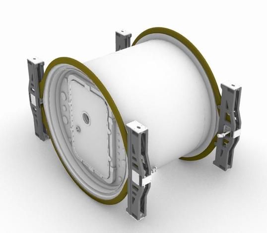
The Multi-Gravity Active-Active Mating Adapter (MGAAMA) is a generic docking system intended to join habitable spacecraft elements in both gravity and microgravity environments. A unique feature of this docking system is that each active end is connected to a central bulkhead via Stewart platforms, such that it is capable of 15-degree offsets in roll, pitch, and yaw between docked elements. This enables not only docking on uneven terrain, but also enables multi-element architectures to follow flexible paths such as around obstacles or even to form a circular arrangement, such as a rotating spacecraft intended to produce artificial gravity. However, this flexibility complicates the floor, which in a natural or artificial gravity environment will need to be load bearing, while also avoiding interference with the Stewart platform actuators. This challenge is to design a floor system that can be contained within the MGAAMA. It must articulate or flex as the MGAAMA adjusts to different angles but must be rigid and load bearing to support suited crew transfer in gravity environments up to full Earth-equivalent gravity.
A successful outcome is a flexible, load-bearing system as measured by the following:
1. CAD model of the flooring system, including any associated linked models (see requirements below).
2. Excel format table listing for each component item the name, quantity, rough dimensions, volume, suggested material (e.g., aluminum, plastic, fabric, etc.), estimated mass, and any associated operating parameters (e.g., power if an electrically powered item).
3. Report in Word format describing the overall flooring system, each component item, and how they should be used in the Multi-Gravity Active-Active Mating Adapter. There are no page length guidelines – it should be sufficient to describe your concept. Include illustrations.
Background:
The Common Habitat is a large, long-duration habitat being explored as part of a feasibility study (not an active NASA program) that uses an SLS core stage liquid oxygen (LOX) tank as its primary structure. Measuring 8.4 meters in diameter and 15 meters in length, it is manufactured as a habitat and launched as such into
space. It is intended for use on the Moon as part of a permanently occupied outpost, on Mars as part of an outpost that will be occupied for hundreds of days at
a time, and in deep space as part of the Deep Space Exploration Vehicle where it will support crewed missions up to 1200 days in duration. A study of internal orientation and crew size resulted in a Common Habitat configuration sized for a crew of eight with a three-deck horizontal orientation. The MGAAMA is used to dock the Common Habitat to logistics modules, pressurized rovers, and an airlock.
An overview of the MGAAMA is found in the paper, A Multi-Gravity Docking and Utilities Transfer System for a Common Habitat Architecture -https://ntrs.nasa.gov/citations/20210020833.
Additional Background:
• Common Habitat Base Camp for Moon and Mars Surface Operations - https://ntrs.nasa.gov/citations/20210020956
• A Common Habitat Deep Space Exploration Vehicle for Transit and Orbital Operations -https://ntrs.nasa.gov/citations/20210021084
• A Safe Haven Concept for the Common Habitat in Moon, Mars, and Transit Environments -https://ntrs.nasa.gov/citations/20210020788
• A Multi-Functional, Two-Chamber Airlock Node for a Common Habitat Architecture -https://ntrs.nasa.gov/citations/20210020897
• Internal Architecture of the Common Habitat -https://ntrs.nasa.gov/citations/20210021782
• Stowage Assessment of the Common Habitat Baseline Variants - https://ntrs.nasa.gov/citations/20205007257
For purposes of this challenge, all hatches shall be assumed to have an opening described by a rounded rectangle, 60 inches in height by 40 inches in width, with a
radius of curvature of 5.9 inches at each corner. All vertical passages between decks have the same size openings – anything that can pass through a hatch on one deck can be transported through a vertical passage to another deck. Vertical passages are generally not adjacent to a wall but are instead near or at the center of the deck. Assume a habitat with 3, 4, or 6 decks and a floor-to-floor distance of 2.5 meters. (Number of decks is a trade study currently in progress and the solution must work regardless of the habitat height ultimately selected.)
Ideas that should be excluded:
● Exclude swapping out of the hardware. (e.g., flat panels of various sizes and pitch angles stored in another module that is positioned as needed). Any solution not common to all gravity environments and all potential orientations of the MGAAMA are to be excluded. Any solution that requires the onboard crew to reconfigure is to be excluded.
● Avoid solutions that are difficult or cumbersome to operate. Imagine having to use this system in your home.
● Avoid solutions that could cause injury or leave crew members trapped or cut off from one another.


Judging Factors
1. Successful designs will meet submission requirements
2. Short description of flexible flooring system and each component item and how they
should be used in the MGAAMA. The description should be of sufficient detail to describe your concept. Include both illustrations and text.
3. Is the design real? Can the design work? Can it actually be created?
4. Meets dimension requirements
**5. If an engineer can provide a simulation of the system, that is a plus but is not
mandatory.
1, The system shall require no reconfiguration or alteration to operate in 0g, 1/6g, 3/8g, and 1g.
2. The flooring system must support the load of two EVA-suited crew members in 1g. (Assume 500 kg as a target mass limit.)
3. The flooring system must be wide enough to facilitate walking by an EVA-suited crew member.
4. The flooring system must accommodate MGAAMA articulation up to 15 degrees in roll, pitch, and yaw. A stretch goal is to accommodate 15 degrees from each Stewart platform, resulting in a total 30-degree articulation.
5. The flooring system shall not decrease its flooring system-to-ceiling height regardless of MGAAMA articulation in roll, pitch, and yaw.
6. The flooring system may not require human intervention to articulate along with the MGAAMA.
7. The flooring system shall be positioned 16 inches beneath the lower lip of the hatch opening.
8. The flooring system shall not preclude the use of wheeled systems to transport cargo through the MGAAMA in gravity environments.
9. The mass for the flooring system must be less than 100 kg.
10. The flooring system may not constrain the motion of the Stewart platform actuators.
11. The flooring system may not prevent the retraction of all Stewart platform actuators in parallel (thereby compressing the MGAAMA length).
12. The flooring system shall be described in a written paper utilizing both text and visuals. Animations are not required but may be included. A CAD model of the flooring system must be provided. CAD files must be provided in a format that can be opened by Rhino 7 or will not be considered for evaluation.
13. Models will be reviewed using Rhino 7. It is therefore strongly preferred that CAD models be prepared in Rhino using NURBS and subject to the following. All components should use Rhino block instancing with linked and embedded files. May involve conversions of models obtained in other CAD formats into Rhino and/or re-modeling of Rhino meshes as NURBS. Models prepared and submitted in other CAD formats will still be fully considered, provided they can be opened using Rhino. (If not saved as a .3dm file it is strongly recommended to include a copy saved as a STEP file.)
The “Download specification” contains a zip file of three simplistic CAD models that may help you in your efforts, but their use is optional.
1. The file “DOC Simple 4x6 to 4x6 MGAAMA Shell.stp” is the notional Multi-Gravity Active-Active Mating Adapter. This is a very preliminary version of the docking adapter that will contain the floor you are designing. The double Stewart Platform in the MGAAMA is notional and almost certainly not the final design. You may discover that it is in the way of your floor. Do not let it affect your design. Because it will change, NASA is not concerned if there are collisions between your floor system and the Stewart actuators. The MGAMMA will, however, give you an idea of how your flooring system will be used.
2.The file “LOG_MPLM_Shell_with_Hatches.stp” is a simple model of a Logistics Module. These units contain supplies that will be used by the crew and in an emergency can also function as a shelter for several weeks. This model is empty (nothing is inside) but it gives you a sense of where the docking interface to the MGAAMA is located.
3.The file “Two-Chamber Airlock.stp” is a simple model of a combination airlock and node that is used in the Common Habitat Architecture. One chamber can be depressurized for EVA while the other chamber remains pressurized to support suit maintenance, supplies storage, and docking to other modules.
An optional demonstration of your flooring system could be to show it inside the MGAAMA with the MGAAMA docked to Logistics Modules and Airlocks. One example might be a docking over uneven surface terrain, perhaps forming a circular base configuration. Another example might be forming a rotating spacecraft for artificial gravity. Showing your floor system supporting different MGAAMAs with varying degree offsets in roll, pitch, and yaw will help demonstrate an effective solution.
ENTERING THE COMPETITION:
Submitting an Entry
AWARDING THE WINNERS
The sum of the Awards is the total gross amount of the reward. The awarded participant is solely liable for the payment of all taxes, duties, and other similar measures if imposed on the reward pursuant to the legislation of the country of his/her residence, domicile, citizenship, workplace, or any other criterion of similar nature. Only 1 award per person. Prizes may not be transferred or exchanged. All winners will be contacted by the GrabCAD staff to get their contact information and any other information needed to get the prize to them. Payment of cash awards is made through Checks mailed to the Winners. All team awards will be transferred to the member who entered the Challenge. Vouchers will be provided in the form of Stratasys Direct Manufacturing promo codes.
We will release the finalists before the announcement of the winners to give the Community an opportunity to share their favorites in the comments, discuss concerns, and allow time for any testing or analysis by the Jury. The Jury will take the feedback into consideration when picking the winners.
Winning designs will be chosen based on the Rules and Requirements schedule.
In order to be eligible for a prize solutions must originate from either the U.S. or a designated country (see definition of designated country at https://www.acquisition.gov/far/part-25#FAR_25_003), OR have been substantially transformed in the US or designated country prior to delivery pursuant to FAR 25.403(c).
Schedule
This Challenge ends on September 7th, 2022 (23:59 EST.) Finalists will be announced on September 14th, 2022 and Winners will be announced on September 21st, 2022$7000 in Total Prizes
$3000
$2000
$1000
$750
$250
Robert L. Howard,Jr., Ph.D. - Habitability Domain Lead
Scott Howe, Ph.D. - Systems Engineer / Space Architect
Dawn Martin, Ph.D., CPE - Flight Crew Equipment - Commercial Crew Program
Tanya Andrews - Human Factors and Integrated Logistics Engineering (HFILE) Team Lead
This challenge is sponsored by the Center for Design and Space Architecture (CDSA),
which is NASA Johnson Space Center’s design studio for human-centered design,
concept development, and rapid prototyping of human spaceflight architectures. The
CDSA team uses sketches, engineering analysis, CAD modeling, Virtual Reality, and
physical mockups to create options for human exploration of the inner solar system.
Have an awesome idea for this competition? Want to win cool prizes? Sign-up now to upload your entries.

If you don't receive the email within an hour (and you've checked your Spam folder), email us as confirmation@grabcad.com.

131 comments
Mercury3D (Tom Leighton) almost 2 years ago
What are the weight bearing requirements for the floor? Will the floor need to be compatible with wheeled devices (like a cargo dolly?..sorry, i mean space cargo dolly).
Vance Benton almost 2 years ago
There is a prize, I will work with GradCAD to update
Robert L. Howard, Jr., Ph.D. almost 2 years ago
Good afternoon, Tom. The challenge was accidentally launched without the full requirements listing. That has been corrected and you may have noticed it by now but #2 in the technical requirements largely covers your question. The floor needs to hold 500 kg in Earth gravity. The flooring system does need to be compatible with wheeled devices. There's a paper coming out this fall where we will be talking about a wheeled system for transporting an incapacitated crew member, so you are right on target with your question. Unfortunately I can't show you any images of that before this competition is over. Don't worry about crossing the hatch threshold, though (the floor is always 16" below the bottom of the hatch - it's a whole other study that set that requirement and dealing with it is outside the scope of this challenge), but any wheeled cargo unit should be able to roll on the floor itself. You could imagine having as test subjects the Mars Pathfinder Sojourner rover joined by some fictional robots: R2D2 from Star Wars, Crichton from Buck Rogers in the 25th Century, and The Robot from the original Lost In Space. If all of these can handle your floor, you have a great solution. Great question! Please keep them coming and to everyone, thank you in advance for your creative ideas!
Tim Khafizov almost 2 years ago
1) What is the minimum area of a spacesuit boot and how close can astronauts stand to each other? This is necessary to calculate the critical loading of the floor structure.
2) During the deployment of the gateway, where should the floor structure be located? (I did not see the requirements for the placement of the floor structure)
Robert L. Howard, Jr., Ph.D. almost 2 years ago
More good questions. (1) The lunar spacesuits are being designed by contractors today, but for a rough estimate, assume each spacesuit occupies a rough footprint of 1 meter wide by 0.78 meters deep. Assume a maximum individual boot size of roughly 0.39 meters long and 0.24 meters wide. (2) I assume you didn't mean to say Gateway - this isn't the Gateway space station. But I assume you mean where is the floor contained within the MGAAMA? The floor system should be a permanently deployed component of the MGAAMA. It should stretch from hatch opening to hatch opening, located 16 inches (0.406 meters) beneath the bottom of the hatch opening. (Each hatch opening is 40 inches wide by 60 inches tall - sorry to mix units, the study that defined hatch sizes was done in standard units while I'm generally designing in metric. Mixed units are the reality of the times.)
Kaleb Wells almost 2 years ago
Hello everyone,
1) What is the required range of retraction and expansion between individual hatches?
2) Is the floor system required to offset roll to maintain normality to gravity? My understanding is that in >0g all decks should already be normal to gravity so the MGAAMA would not need to roll in >0g.
Kaleb Wells almost 2 years ago
3) What axis are pitch and yaw measured from? Is it the internal axis of each hatch or the axis of another hatch?
Tim Khafizov almost 2 years ago
I formulated the second question incorrectly. I will try to rephrase: What is the requirement for the installation of the floor being developed (automatic during the installation of the Spacecraft Docking Adapter or manual)?
Bobby Weber almost 2 years ago
The ring diameter shown around the hatch opening doesn’t appear to accommodate the floor offset of 16 inches - can you provide the ring diameter or is this a variable the we control for the specified placement of the floor? Thx
Marc Samarra over 1 year ago
Same question as Bobby Weber before me. 16" below hatch threshold it's already outside the outter ring.
Are we supposed to ignore the CAD file provided and design something theoretical?
See dimension pic here: https://ibb.co/z4WW4PC
Also, how wide must the flooring be? Same as hatch opening span? wider or narrower?
Thanks.
Bobby Weber over 1 year ago
Unless there is an error with units (mm instead of inches?), the challenge requirements as written are unworkable. With stated floor placement there will not be any wheeled equipment rolling through the MGAAMA without lifting over the hatch lips and everything (and everyone) will be dancing over the Stewart struts. My apologies if this is just the simple error in units but otherwise a comprehensive rework of challenge requirements by the project originators is needed.
Robert L. Howard, Jr., Ph.D. over 1 year ago
Several people asked about the hatch-to-floor distance. I probably shouldn't have even brought it up because there is an issue in the current model. The current floor is 11.38 inches below the hatch, which is not the correct value. I decided to not redesign the entire MGAAMA until I had the floor system (and several other identified problems) solved. The floor should be hidden in your model, but don't worry if it displayed when you imported the STEP file. (This is not the only issue that needs to be corrected, but none of them directly impact this challenge.) You have three choices that are equally fine:
Option 1, use the current floor height. Don't worry about the fact that the floor is in the wrong position.
Option 2, scale up the MGAMMA model until the 11.38-inch distance is increased to 16.
Option 3, as Marc suggested, ignore the CAD models completely and design a system that can be incorporated into a pressure vessel.
I'm more concerned about the mechanics of how your floor is designed than its placement in a model that is useful for illustration but already requires redesign. Use the models if they help you, but their use is not required.
In terms of floor width, there is no maximum, though I doubt any solution will exceed hatch width. A likely minimum is 24 inches. That being said, the floor width will eventually be scaled to fit the redesigned MGAAMA, so it would be best if the flooring system will work with floor widths that vary from 24 inches to 40 inches. If you design to only one width, 30 inches is a safe width to use.
Robert L. Howard, Jr., Ph.D. over 1 year ago
Tim, if I understand your question correctly, the flooring system should be installed during manufacture, not in space. It should be launched in a fully-deployed and operational configuration. Note that the MGAAMA will be used in fully autonomous spacecraft docking and undocking. Crew should not be required for any activity associated with docking or undocking other than to open/close the hatch when they pass through a module.
Tim Khafizov over 1 year ago
Yes, you got it right. Thank you for your answers. I'll try to make it on time.
Robert L. Howard, Jr., Ph.D. over 1 year ago
Robert, I'm not imposing any material restrictions, so you can use polypropylene.
Robert L. Howard, Jr., Ph.D. over 1 year ago
Kaleb, for your question number 1:
There are no range requirements. Do take into account that the hatch is 40 inches wide and will need to open into the MGAAMA passageway.
Robert L. Howard, Jr., Ph.D. over 1 year ago
Kaleb, for your question number 2:
Yes, the floor system must offset up to 15 degrees in each of three axes: roll, pitch, and yaw. Keep in mind that this same docking system will be used for both fixed and mobile elements on off-road terrain. For instance, you could have two rovers (with side-mounted docking ports) next to each other on uneven terrain. One rover might be pitched up while the other is pitched down. This would create a need for the MGAAMA to offset roll.
Robert L. Howard, Jr., Ph.D. over 1 year ago
Kaleb, for your question number 3:
Roll, pitch, and yaw should be measured from the center of the MGAAMA.
Lucas Martin Dublanc over 1 year ago
Argentina?
Germano Pecoraro Designer over 1 year ago
Italy?
Oleg P. over 1 year ago
Ukraine is available?
Amine Hamdi over 1 year ago
Tunisia ?
Javodbek Dadajonov over 1 year ago
Uzbekiston?
bagoespn over 1 year ago
https://www.nasa.gov/sites/default/files/atoms/files/designated_country_list_8-16-2019_tagged_0.pdf
Aston Zhang over 1 year ago
What is the range that the floor must expand and shrink to?
david surridge over 1 year ago
Is it expected that the floor remain parallel to the various hatch openings throughout the length of the MGAAMA? Based upon the functional description and requirements it seems this would imply it could take on a fairly substantial twist. Or is it expected that the floor remain relatively flat, but allow the MGAAMA to twist/yaw/roll around it? This would then mean the floor would not remain parallel to the hatch openings but perhaps be easier to walk on, roll equipment, etc.
Robert L. Howard, Jr., Ph.D. over 1 year ago
Aston, you ask a good question that does not have a clear answer. It's not so much a requirement for a specific expansion or shrinkage of the floor as it is an accommodation of the articulation. The Stewart platform can be implemented in many different ways, which would change the length of the individual actuators. The simplest thing for you to do is to model the actuators in the MGAAMA CAD model and estimate the maximum retraction experienced by any one actuator to achieve a 15-degree articulation in roll, pitch, or yaw. Then calculate the reduction in floor length that would be experienced if all of the actuators retracted to that amount. Maximum floor length would follow the same process, but look at actuator extension instead of retraction.
Robert L. Howard, Jr., Ph.D. over 1 year ago
David, the key is going to be protecting the floor to ceiling height so that you don't induce choke points where tall crew or tall objects cannot get through. Yes, there might be twist in the floor and/or MGAAMA. Both could be allowed.
Mercury3D (Tom Leighton) over 1 year ago
I've rewritten this sentence a few times this is my best attempt at asking this hopefully it makes sense: When the openings are at a 15 degree roll to one another, the top of the floor should be parallel with the bottom of the hatch opening ? (i.e. the floor should be able to articulate a 15 degree roll, but not "twist". Correct?) You want the floor to be "Flat" at all times right?
Paul Kyum Lee over 1 year ago
I also have the same question as Tom.
Allan over 1 year ago
In terms of module deployment on the surface of terrestrial bodies, are there limits on the slope of the ground (in any axis) that each docked unit can be placed? I assume this relates to the degrees of freedom of movement the Stewart Platform has in each axis but that module placement should come to within a certain design limit of the maximum available travel in each axis. For example two docked units could be on ground where one is level and the other slopes away in one or more axis directions. Ground Slope Max would = X minus Limit degrees. Where X is the degrees of freedom of the actuator and Limit is the Delta between the slope of the ground being considered and the maximum actuator travel. This gives a margin of safety for the actuator travel, deployment physical limits for each docked module pair wrt ground slope and ultimately the Floor (design target) plane. Thus what is X for each axis?
Doug S over 1 year ago
Hello Dr. Howard. I have a few questions. Will the two end hatch walls always be parallel to each other? Will the two hatch wall center axii always be colinear to each other? Will the two end hatch walls be a fixed distance from each other? If the answer is no to any of these questions then is the cylindrical outer enclosure flexible in some way? Lastly, should there be two independent floors due to the center hatch being completely circular or one floor and assume the center hatch is sectored by a chord with the flat edge mated to a singular floor? I think the answer to these questions will help me to visualize more of what the requirements of the floor are. Thank you.
Allan over 1 year ago
11. The flooring system may not prevent the retraction of all Stewart platform actuators in parallel (thereby compressing the MGAAMA length).
This will impact upon the maximum length a floor section can be when the MGAAMA is in the fully retracted or 'stowed' position.
What will be the approximate maximum length of the overall platform between the outer docking sections, (measured perpendicularly to the vertical axis of the centre bulkhead) when fully retracted.
Deerspotter over 1 year ago
Everyone is overthinking this. Use load bearing struts as part of the floor system. It doesn’t have to be a floor that doesn’t have any gaps.
Allan over 1 year ago
"10. The flooring system may not constrain the motion of the Stewart platform actuators."
"The double Stewart Platform in the MGAAMA is notional and almost certainly not the final design. You may discover that it is in the way of your floor. Do not let it affect your design. Because it will change, NASA is not concerned if there are collisions between your floor system and the Stewart actuators."
These two statements in the spec above seem to be contradictory. Whilst the example of the MGAAMA is notional; to comply with Point 10, if the floor design collides with the actuators then they will need to be included in the floor design iterations to prove the floor works within the constraints of the internal MGAAMA volume and the placement/connections of the actuators.
So are we to ignore any collisions or design the actuators as well to prove the floor works in accordance with Point 10?
george aziz over 1 year ago
7. The flooring system shall be positioned 16 inches beneath the lower lip of the hatch opening.
Question 1:
is that means that the floor level shall be 16 in beneath the lower lip of the hatch opening. or the floor level shall be in the same level as the hatch lip and the rest of the system is 16 in beneath the lower lip of the hatch opening
Question 2:
the middel hatch ring is it part of the design or we have to ignore it (Stewart platform) and the floor system is connecting only the two main hatches ,can we ignore the whole stewart platform or ignore just the actuators
Allan over 1 year ago
Is the requirement for 15 degrees of motion in each axis the total travel about each axis i.e. 7.5 degrees in each direction for a total of 15; or 15 degrees in each direction for a total of 30 degrees? In other words if I pulled back on the stick in an aircraft should my max pitch up be 7.5 or 15 degrees and vice versa?
Hamza Alhaniny over 1 year ago
does the the flooring system include walls and ceiling?
Joseph Gallagher over 1 year ago
Is the design required to maintain load-bearing capacity while in motion, or is it okay to have a distinct "flexible mode" and "rigid load bearing mode" as long as transitioning between them can be done quickly and does not require human intervention? When in use for transit by crew or cargo, what is the range of temperatures and level of pressurization/vacuum within the MGAAMA that we should design to accommodate? I have a few interesting ideas based on material phase transition and want to make sure that they're workable
Robert L. Howard, Jr., Ph.D. over 1 year ago
Joseph, the design must maintain load-bearing capacity while in motion. One use case is as the mating adapter for modules in a rotating, artificial gravity space station. A multi-module mobile surface habitat could also use the mating adapter. In both cases, crew would use the adapter to pass between modules while the vehicle is in motion. The pressurization can vary from 0 psi to 14.7 psi. Nominal cabin temperatures would comply with NASA-STD-3001 or any other ECLSS requirements, but it should remain viable across a wider temperature range. Temperature requirements have not been written yet, but I would expect water in the utilities to freeze or boil long before the MGAAMA fails due to some temperature extreme.
Robert L. Howard, Jr., Ph.D. over 1 year ago
Hamza, no, the flooring system does not include walls or ceiling, just the floor. The interior surface of the MGAAMA can be assumed to constitute wall and ceiling surfaces.
Robert L. Howard, Jr., Ph.D. over 1 year ago
Allan, the 15-degree requirement is 15 degrees in either direction. In other words, if you pull back on the stick in an aircraft, the max pitch up is 15 degrees. Or if you push forward, the max pitch down is -15 degrees.
Robert L. Howard, Jr., Ph.D. over 1 year ago
George, for Question 1, the floor level is 16 inches beneath the lower lip of the hatch opening. In other words, when you are standing on the floor, the lower lip of the hatch opening is 16 inches above the bottom of your shoe. For Question 2, the middle hatch ring is part of the design. I suppose you could split it into two middle rings and move each closer to the outer bulkheads if that helps your design in some way. I'm giving some leeway on Requirement #10 - no interference between the floor and the Stewart actuators. They were supposed to get a redesign, but the resources to do so did not materialize in advance of this challenge. You can feel free to take that on if you want, or if you want to work around them, please do so. However, I am more interested in seeing a flooring system that can support a load while still accommodating the changes in roll, pitch, and yaw.
Robert L. Howard, Jr., Ph.D. over 1 year ago
Allan, you and George had the same question. Originally, the intent was to force you to work with the actuators, but the resources were not available to complete that redesign in advance of this competition. So, you can (1) completely ignore the actuators; or (2) redesign the actuators; or (3) design a flooring system that works around the current actuators.
Robert L. Howard, Jr., Ph.D. over 1 year ago
Deerspotter, you are sort of onto something. We haven't defined the smallest wheels that might roll across this floor so it's hard to give you a maximum gap size. A safe bet would be if you can roll an office chair or a utility cart across the floor then it is probably sufficient.
Robert L. Howard, Jr., Ph.D. over 1 year ago
Allan, the retraction has not been defined yet. It is driven, though, by the Stewart Platform. There is no driver to maximize the length of the MGAAMA; more the opposite - a desire to minimize its length. You can model your own Stewart Platform and explore the potential maximum and minimum lengths given the +- 15-degree offsets the platform is enabling.
Robert L. Howard, Jr., Ph.D. over 1 year ago
Doug, the two end hatch walls are NOT always parallel to each other, their center axes are not always colinear, and the two end hatch walls are not a constant difference from each other. The cylindrical outer enclosure is most likely an inflatable structure. One minor note, the outer enclosure and bulkhead walls are circular, but the hatch is a rounded rectangle - 60 inches tall by 40 inches wide. There are possibly two independent floors - one on each side of the center bulkhead, but it is possible there are other solutions.
Robert L. Howard, Jr., Ph.D. over 1 year ago
Allan, the MGAAMA does not care what slope each docked unit is placed on. However, the 15-degree offset does limit the difference in slope between two docked spacecraft. For instance, if two rovers are docked on a surface right where its slope changes from 10 to 40 degrees it would be at its maximum reach (with both sets of Stewart Platforms at 15-degree pitches) but should theoretically be able to dock. But if the slope changes from 10 to 42 degrees that would exceed its capacity and it would not be able to dock.
Robert L. Howard, Jr., Ph.D. over 1 year ago
Tom and Paul, a roll offset is going to require some degree of twist. The floor will only be perfectly flat when there is 0 degrees offset in roll and pitch. It hypothetically could remain flat in pure yaw offsets, but there might be some change in flatness even there. One might assume that the end of the floor that is fixed to the end bulkhead is always parallel to the bottom of the hatch opening (and it certainly can be), but it is possible there might be a design where this is not so.
Allan over 1 year ago
Thanks Robert, regarding retraction of the actuators. If for example you could retract the MGAAMA to 1M in total length, i.e. 500mm either side of the centre bulkhead, then the limit of extension could only be twice the closed length since each actuator (similar to a hydraulic arm) could only slide out by the total length of its inner piston.
Whilst aiming for the smallest envelope in a 'stowed' configuration this limits the total possible deployed length somewhat.
Since you require scenarios where wheeled trolleys/carts etc can be pushed along the floor design and you mention an office chair for simple example, when you consider the horizontal deployed length required for a suited crewman and the item he is moving along the floor to egress from one docked vehicle into the MGAAMA , through the centre bulkhead then traverse the second section and exit into the other docked vehicle then the human factors and ergonomics come into play.
Thus rather than specify the minimum length of the unit in stowed config there must be a minimum deployed length such that crew and loads can be successfully manoeuvred through the docking portal.
Only then can we design the flooring system since the max deployed length to enable adequate ergonomic use effects the length of actuators required, the load on them when deployed to full extension but most importantly since the central axes changes from being collinear in 0 deg of pitch and yaw to being off axis the height delta between the floor at the entry point and centre bulkhead changes significantly.
Sorry for the longwinded thought process but have you specified the minimum deployed length measured either side of the centre bulkhead to each outer docking mechanism to allow for practical use?
Specifying this will also mean each designer is working within some parameters that will mean you are accurately comparing each design.
Allan over 1 year ago
Is it possible to have some form of legs that support each outer bulkhead when the MGAAMA is deployed on the ground? These could both support the structure at either end of the platform but also used to provide some levelling to compensate for roll angle between docked units or more importantly difference in height on the horizontal plane between two dock vehicles; or two vehicles or platforms which vary in the height of their respective exit hatches. The legs could be retractable to reduce envelope in stowed config? If possible I think this can help design a less complicated floor? Maybe I can model this with and without to demonstrate the advantages??
Flaviano Crespi over 1 year ago
Hello Mr Howard, In order to help understand the problem and share the concepts with the Gradcad design community I would like to ask you if the considerations I have published here:
Oscillation limits
are correct regarding the swing modes and the position of the walkway.
Thanks in advance
Allan over 1 year ago
In response to Flaviano and note to NASA too. Great graphics FC. I had originally modelled this the same way, with the centroid of the rotational axis for pitch, yaw and roll placed at the centre of the circle of the inner bulkhead. On reflection I moved this to the centres of the outer bulkheads. If it is placed wrt the centre bulkhead it creates a moment arm the length of the distance between the inner and outer bulkhead. This changes the way the outer face plane of the outer modules moves quite drastically. I believe you can still technically meet the design requirement for 15 deg movement + or - of each axis if the outer bulkheads rotate about their own centroid. NASA needs to clarify however where the measurements are taken from. I will post a visual of my interpretation shortly for comparison. I have made the circumference of the bulkheads greater to take account of the floor being 16" below the entrance lip. That way I can note any interference with the Stewart actuators.
I believe it is possible to keep the centre bulkhead x, y and z axes fixed whilst the outer bulkhead moves about its own centre to achieve +/- 15 degrees of movement.
NASA can you please comment. Depending on how you set the datum for measuring the angles changes the design problem considerably. Thanks
Flaviano Crespi over 1 year ago
@ Allan and NASA,
Yes, actually placing the axles on the middle bulkhead results in very strong lateral compressions, but I don't think it changes substantially by moving them to the front bulkhead. I'll check it out.
Thanks Allan for the note.
It is really important that NASA confirm what the standard distance between the disks is, Logically it should be that of the model they provided and quoted in the sketch I published.
Allan over 1 year ago
@ Flaviano and NASA I agree thats why after commenting to NASA about the ergonomics and human factors I have decided to lengthen the distance between the centre and outer bulkheads such that there is sufficient room for a suited crewman; (with or without stowed kit/trolleys/carts being pushed on the floor), to walk through each section of the portal and step over the hatchways. This means lengthening the actuators as well. There is an ideal distance between centre and outer bulkheads at which even with the outer bulkheads at full pitch and yaw the 'pinch' is not great enough to cause the actuators to bottom out nor I believe the outer flexible air tight skin from bunching to the point at which it restricts the travel of the moving bulkhead. But it begs the question about the design task and whether they have the cart before the horse! I have appended pics to my entry too.
Doug S over 1 year ago
Thank you Robert for the answer to my first question. This helped me to visualize this and I have a good idea about what is required for the pitch. I do have two more questions. What is the maximum distance that a hatch door is expected to be from one another and what is the minimum expected difference. I am referring to minimum and maximum floor span. Thank you.
Allan over 1 year ago
What is the distance between all bulkheads? This must be known by designers otherwise how can you meet the weight limits of a floor design. If someone uses the original supplied Simple Model then the overall length was around 78 inches. Not enough room to open the hatch inwards without hitting the inner bulkhead! OK lets assume 44-48 inches between centre and outer bulkheads, (there was an earlier answer to this effect for Doug S but seems to have been deleted??); is this the deployed length? If so how do you fit in this space and push something on wheels?
Also the length impacts the floor design and its subsequent load bearing capacity. This has been specified as a requirement for the design. How can designers work to this weight bearing capacity if I design something say 1.5m long vs someone else designing a longer or shorter floor. I know the intent of the exercise is to solve the problem of the difference in relative axes for a floor and you have said to ignore some of the physical constraints based on a complete redesign of the portal and stewart mechanism however this then becomes more of a brainstorming exercise than an engineering design. Either you have specs that inform the design or have complete leeway. Which is it? I can't see you can have it both ways NASA. Yes there is a level of frustration here!
Robert L. Howard, Jr., Ph.D. over 1 year ago
Allan, you definitely have a good grasp of the challenges involved in this problem. One note about your assumption of the limit of extension being twice the closed length. You assumed a two-stage cylinder solution. That is reasonable and matches every Stewart Platform I've seen, but up to 5-stage cylinders do exist in industry; I just don't know if they've ever been used in a Stewart Platform application (or if there there would be any need to do so).
Allan, with respect to the legs I would prefer to see a solution without legs, but I see why it would be appealing to you in terms of supporting the structure. I don't think it helps as much as you're thinking, though. And it could become rather complicated to design legs that could accommodate all of the possible variations in angle and terrain.
Flaviano, yes, you have done an excellent job representing the swing modes and walkway position. I see you showed the increase needed to accommodate the 16-inch stepover. As an aside, the 16-inch stepover dates back to a hatch study under the Constellation program where structural engineers were advocating for the smallest opening possible. (The larger the opening in a pressure vessel the more massive it becomes.) A 60-inch tall by 40-inch wide hatch with a 16-inch stepover was shown to be possible. It forced a suited crew member to bend over (to get below the top of the hatch opening) while side stepping (to get the foot above the bottom of the hatch opening). From a human performance perspective, a significantly larger hatch is desirable, but this was the compromise that has become a de facto standard in the past 15 or so years. (Arguably, the center bulkhead can have a larger opening since it is not currently envisioned as a pressurized bulkhead. There is a potential growth path where it might serve as such, but that's not the current iteration of the MGAAMA.)
Flaviano and Allan, for the location of axes to measure the angles, let me take a step back and give an example that illustrates the intent. Consider as a starting point the Nautilus-X spacecraft concept developed back in 2011 or so. But replace the rotating wheel with a system of a dozen modules, docked together by MGAAMAs. This would represent a 30-degree change in pitch between each module, meaning within each MGAAMA both Stewart Platforms are at their full 15-degree extension in pitch. That's the performance you're trying to achieve.
Doug, Allan, and Flaviano, you have all essentially asked for minimum and maximum distances between the outer bulkheads and center bulkhead. There is no requirement that sets those. There are some implications of that distance, but there is no requirement. Clearly, the outer bulkhead cannot be allowed to hit the inner bulkhead at a 15-degree angle. And as Allan pointed out, there must be enough room between bulkheads to maneuver. In many ways, shorter is better, but too short is nonviable. You should make your own length determinations, like Allan took the initiative to do.
Doug S over 1 year ago
Thank you Robert. I will design for the constraints as put forward.
Allan over 1 year ago
Thanks Robert appreciate the feedback. Ill refocus and put aside my frustration. I have modelled so far using a two stage cylinder and this seems to limit the min inter-bulkhead distances to around 1.1m. Too close for the inner door to open without collision but that could be a stowed position i.e. whilst not in active use. But it also limits the ability to achieve max 15 degree movement in all axes when you take into account the larger diameter bulkhead size required to achieve the lowered 16" floor placement. Thus it would appear that more than two telescoping cylinders will be needed in the subsequent portal re-design exercise. Having three cylinders gives greater flexibility for deployed length such that you could have the larger dia bulkheads and circle the wagons as it were if required. The added benefit is space to manoeuvre through the portal when docked. I must admit I have been hung up on these elements and have not devoted enough effort into the floor design. After all that is the challenge not to redesign the Stewart Platform and MGAAMA itself. Notwithstanding I hope my observations and thoughts are constructive in that eventual exercise. Regards
Flaviano Crespi over 1 year ago
Thanks Howard for the clarifications. In practice we have to worry about the design of the flexible floor only taking into account the implications of the optimal distances of the bulkheads. I have a further question regarding the mass of the flexible floor; since they are essentially two equal pieces, is the limit of 100 kg for the single piece or both?
Allan over 1 year ago
There has been some discussion about the centroid axis around which the outer bulkhead rotates in x, y and z. Either its own or the centre bulkhead. I have spent some time, (in all honesty too much), modelling the Stewart Mech so that I can understand its full articulation with respect to the impact upon the floor and its design. In the ref PDF cited it shows two rovers docked together side by side. It looks as though they are at different heights in the horizontal plane. It appears that the Stewart mech can move up and down in the vertical axis whilst the inner and outer bulkheads remain parallel with each other. The height delta is dependent on the length of the actuators. The longer they are the greater the moment arm between inner and outer bulkheads. Question. In the ideal situation what would be the difference in height achievable between two docked elements?
Robert L. Howard, Jr., Ph.D. over 1 year ago
Allan, one thought - please don't put time into this because it isn't the priority of the challenge, but wanted to put it in your mind. We usually assume a hatch is an aluminum, flat plate. That is entirely reasonable and fairly normal, but at least one company to date has explored the idea of an all inflatable airlock. Even their hatch was fabric: https://www.cfd-research.com/cfdrc-wins-nasa-contract-to-design-a-light-weight-inflatable-structural-airlock-lisa/. I don't know what became of their effort, but I think there are multiple ways to deal with hatch interference. Bottom line, put a little thought into how to deal with the hatch but don't turn this into a hatch accommodation challenge. That can be solved another day.
Robert L. Howard, Jr., Ph.D. over 1 year ago
Flaviano, the mass of the total flooring system must be 100 kg or less. If the two sides are equal, then each has a 50 kg limit.
david surridge over 1 year ago
When I imported the 4X6 MGAAMA model the circular end structures with various gears and shafts at sides appeared to have been scaled non-uniformly. In fact, the entire model might have been nonuniformly scaled, but it's easiest to see on those structures. The gears, bearings, etc. are oval shaped. Were the models uploaded that way or is this some kind of import error on my end? I can't say I've ever seen an imported model do this. I looked through the previous comments. It did not appear that this issue had been raised, but my apologies if it has.
Adam Kooperman over 1 year ago
This guy made it Flaviano Crespi
Revised clamp ring
Robert L. Howard, Jr., Ph.D. over 1 year ago
Allan, which figure on which pdf are you looking at? Sorry, got distracted by work. As a general statement it is always ideal for two elements to be at the same height, but that is not something that can be guaranteed on an off-world surface. That being said, I did not make a height adjustment part of these requirements. I expect if there had been such a requirement it would also impact your floor lengths and could possibly complicate the Stewart Platform design beyond just their lengths, but I don't want to add that to your plate.
Allan over 1 year ago
Thanks Robert it was just the MGAAMA PDF showing two rovers docked side by side.
Paul Kyum Lee over 1 year ago
Hello, is ease of manufacturing a significant criterion? And should our designs be fully manufacturable? (proper tolerances, BOM with off-the shelf parts, etc.)
Faraz Shiekh over 1 year ago
Hi Guys, Having read through the comments could not find where does the docking system need to be rotated for its pitch, roll and yaw rotation.
Is this the centre of centre bulkhead or from the centre of moving part itself?
Flaviano Crespi over 1 year ago
@ Faraz Shiekh , My opinion:
Centroids position
Faraz Shiekh over 1 year ago
Thanks @Flaviano
John over 1 year ago
Is there an allowance for maximum trip hazard height such as when one element of floor material slides over another at the point of articulation
John over 1 year ago
Can the docking adapter be used to change the distance between the module flanges in order to compensate for articulation geometry changes such as occurs with yaw adjustment (twist)
John over 1 year ago
Can the actuators of the MGAAMA be programmed to operate about a centroid of rotation so the platform is symmetrical?
jesse mailloux over 1 year ago
YES CHECK OUT MAILLOUX JESS
John over 1 year ago
What is the maximum and minimum distace between connecting flanges of the MGAAMA
Robert L. Howard, Jr., Ph.D. over 1 year ago
John, the distance between connecting flanges of the MGAAMA will be a feature of your design. There are no minimum and maximum requirements. Clearly, the flanges should not strike each other when rotating, so the pitch and yaw rotations will give you a minimum possible distance. Other than that, do consider usability - there should be enough room for a crew member to maneuver (open hatches, step, etc.). But no sizing study has been done to define hard limits. Yes, the actuators can be programmed to operate about a centroid of rotation. Yes, you could use the docking adapter to change the distance between the module flanges.
Robert L. Howard, Jr., Ph.D. over 1 year ago
John, for your question about trip hazard height, it is not necessarily a given that one element of the floor material will slide over another. If you do use such an implementation, then you would want to ensure that the floor material is not a trip hazard itself. You will need to decide how to ensure that to be the case.
Robert L. Howard, Jr., Ph.D. over 1 year ago
Faraz, you can choose where you want the docking system to rotate. The consideration is that the two elements to be docked may be offset from each other by 15 degrees in any axis. The docking system has to accommodate this misalignment. As long as the flooring system can do so, you have satisfied the design challenge.
Robert L. Howard, Jr., Ph.D. over 1 year ago
Paul, since this is a feasibility trade study, it is a nice to have, but not mandatory, that your designs be fully manufacturable. It certainly would make follow-on work easier, but at this point we are trying to answer the fundamental question of is this even possible. I recommend that you always design for ease of manufacturing. And of course, a system that is clearly easy to manufacture goes a long way towards demonstrating feasibility, so I think that is beneficial. It is, however, possible to fulfill the requirements of this competition without doing so.
Robert L. Howard, Jr., Ph.D. over 1 year ago
Allan, for the rovers, were you referring to Figure 10 in https://ntrs.nasa.gov/citations/20210020833? That one is probably one of the best images I have showing two rovers docked. They were at close to the same height, but the ground is not perfectly level. This image is actually a good case - it can be worse. These particular rovers have an active suspension that helps significantly to compensate for misalignment in the vertical direction and roll, and to a lesser extent in pitch. Their steering can also eliminate most misalignment in yaw. Not all surface systems have the degree of flexibility this rover has, though.
Allan over 1 year ago
Robert regarding model format. Im using Solidworks 2022, you may need Rhino 8 to open that. Rhino 7 will open SW up to 2021. I think I can save to a Rhino format but unsure. Problem is that all the actuations etc require some complicated Mates in the assembly. None of these come through when you save to a step file. So you get a dumb model to evaluate. Like others I have some animations that hopefully will show the appropriate operation.
Doug Tinney over 1 year ago
I've been unable to load the required Excel and Word documents. The web page says that the 'file type is not allowed.' What is the best way to do this? If PDF format is acceptable then how do I update my posting?
Allan over 1 year ago
Yes and it says EST when US is currently in EDT
Allan over 1 year ago
Yes and its EST when USA is currently in EDT
Vochitoaia Marian over 1 year ago
If a pneumatic pillow can lift a block of concreate, can't a "Michelin man" do some " asymmetric" exercise to align the hatches ?
Vochitoaia Marian over 1 year ago
In stead of the Stewart platform, we get "Michelin man"
Paul S. over 1 year ago
Me too, I planified my work schedule for the delivery shortly before the stated deadline : « This Challenge ends on September 7th, 2022 (23:59 EST.) »
Which is tomorrow, not tonight !
Kesa over 1 year ago
We have fixed the timer issue. Thank you all who reported it.
Brien Allison over 1 year ago
Ah it didn't apply the NASASPACECRAFTDOCKING tag automatically when I published my model, so I missed the deadline. Nevermind, I don't think I would have won anything anyway. My design is on my account is anyone is interested.
Aston Zhang over 1 year ago
I had a lot of fun working on this challenge. Good luck to all of you, and may the best design win!
Faraz Shiekh over 1 year ago
Any update on the finalist model selected? It mentioned finalist will be announced on 14th Sep.
Orestes Barredo over 1 year ago
thank you for this event and good lock to all of us
Bobby Weber over 1 year ago
Any news you can share on the finalists or when you anticipate the announcement? Thx
Marcelo Valderrey over 1 year ago
Is this silence part of astronaut training to control anxiety?
As a mere mortal, I'd say it's not working!
LOL
Don't worry, no one is anxious (lie!).
Kesa over 1 year ago
Finalists are Live. Sorry for the delay
Nazarii Vareshchuk over 1 year ago
I hope you take into account the sequence of publications when analyzing. And then there are developments that are 90% similar to mine, and if you read the description of my development, then 99% will be.
And they were published much later.
In any case, thanks.
Marcelo Valderrey over 1 year ago
This morning my proposal (Scissors: design and calculation memory) was among the 10 shortlisted out of a total of 57 entries. Now my profile is empty (no models or tutorials) and my proposal does not appear in the challenge (and it reports a total of 56 entries).
Can someone explain to me what happened? (sorry, I'm new to GrabCad).
Best regards!
Marcelo Valderrey over 1 year ago
Houston, we have a problem...
I fear that we are in the vicinity of a black hole, which yesterday made my GrabCAD work disappear and also swallow any attempt to communicate with the earth: no one acknowledges receipt of my communications, no one answers, no one...
support@grabcad.com ...not responding
info@grabcad.com ...not responding
GrabCAD Community User Group ...not responding
What I can do? (I don't have much oxygen left! LOL)
R 1 over 1 year ago
@ Marcelo Valderrey - If you had anyone like or comment on your design, contact them and ask them to place a comment here indicating their memory of your design. Also, upload another copy to your account so that it is there at least.
Marcelo Valderrey over 1 year ago
@ R 1 - Thank you very much for your answer.
My work had a few likes, questions and comments but I don't remember the users (I'm new to GrabCAD). However, I did take a screenshot of the finishers screen where it appeared...
Maybe if I upload something, the users who saw it can support me and make a comment (I don't want to make a problem with this either, but "someone from the staff" gives me signs of life).
Again thank you very much!
Nazarii Vareshchuk over 1 year ago
@ Marcelo Valderrey - I think I found a screenshot where your development may be present. check it out But I don't know how to send it to you, it's not possible to attach a file here.
I will try to send it to you personally.
Nazarii Vareshchuk over 1 year ago
@ Marcelo Valderrey
I added this as a comment to your model:
https://grabcad.com/library/in-memory-of-scissors-design-and-calculation-memory-1
Marcelo Valderrey over 1 year ago
Thank you very much friend!
Paul S. over 1 year ago
Dear Sr. Valderrey,
If I recall correctly, when first published, the images of your concept didn’t show on my screen.
In order to verify that my own work in progress wouldn’t duplicate any original idea already published by a contestant, I downloaded this file : “ design-and-calculation-memory-1.snapshot.35.zip “ (47322 KB, time-stamped 8/29/2022 8:33 PM).
With my old SW 2018 I couldn’t open the Solidworks files, but a quick review of the presentation document in PDF made me conclude that I wouldn’t be infringing, so I didn’t bother with the step files to further investigate.
I wish to compliment you on the quality of your 25 page long presentation. Really well done.
I reviewed it now and I would call the attention of the evaluators to your statement on page 19 : « As the total weight of the floor (36.39 Kg) is well below the imposed limit (100 Kg), it is possible to consider alternatives with a greater number of scissors, which are closer to each other. ».
Indeed, my first impression was : that walkway might be somewhat “spongy” and there could be some tripping hazard when it is fully extended. So, more scissors would help with those issues.
I would dare a little suggestion : you need to further explain the limits on the side torsion of the scissors when a smaller footprint load, such as a wheel of a stretcher would ride between the vertical scissors, not directly on top of them.
My own concept attempted to accommodate a stretcher and an astronaut - handler, with enough room to manoeuvre over the three thresholds, so my proposal was a larger walkway, when fully extended, within a modified Stewart platform system, also accommodating a larger swivelling of the walkway in all plans. There was a consideration paid to the walkway’s integrity, if the platform was left attached to two vehicles moving over uneven terrain.
With the last day uncertainty about the actual deadline, I switched to another urgent undertaking and I didn’t finish the submittal.
If it would help to confirm your timely participation in the contest, I could email to GrabCad the actual zipped file, with your documents in it, that I downloaded from their site.
Best regards,
Paul S.
Marcelo Valderrey over 1 year ago
Hello dear Paul,
When I started uploading my work, I didn't handle the GrabCAD platform well and for a while I only uploaded models that weren't seen in the gallery! And also the first version of the calculation memory.
My model was from Solidworks 2017, but I also uploaded several STEP files so that anyone can open it (and also to fulfill the request of the challenge, since I don't have the preferred software Rhinoceros 7).
As the days went by I generated some animated gifs, and also some rendered images, in addition to updating the memory until its version 2, and then 3 (which ended up having 28 pages and I think also some of the clarifications to your comments).
Another user had asked me about the lateral buckling of the scissors and other details that made me notice that clarifications were missing in the memory. I incorporated the alternative with the highest number of scissors and added an explanation about the limits of their lateral rotation, among other things. I just forgot to mention the possible addition of a soft cover mat or carpet, in case the support surface was not suitable for all purposes.
I thank you very much for all your valuable comments and, although I have no real expectations for the work presented, I would like it to at least be taken into account since it reached the pre-selection stage.
Thank you again!
Kind regards from Argentina.
Paul S. over 1 year ago
Estimado Señor Valderrey,
I don’t see why would your entry be erased from the challenge.
Most likely a computer glitch or a malfunction while someone at NASA was downloading your files for the final review.
For it isn’t easy to assess the feasibility of the proposed schemes, without a thorough motion simulation with the native software, over the full range of twists, turns and stretches. I don’t see how that could be done in the context of surface modelling with the Rhino (but I don’t know that software).
It took the NASA crew longer time, since it takes a lot of work, to complete the pre-selection. I trust that the thorough final evaluation will cause even more sweating.
From the looks of it, they wanted to get the new pre-engineered concepts to complement their own preliminary design solutions for the physical networking of their outposts. Then develop the best candidate(s).
In return, I trust NASA is performing a fair evaluation of the contest entries and for that they need to invest a lot of time and resources, considering the lack of explanations / details in several submissions.
To increase the lateral stiffness of your walkway, did you consider offsetting and overlapping the rungs on top of the scissors and somehow tie them together ? That would likely increase the retracted sideways projection of the walkway.
I don’t know whether NASA is considering that issue at all.
In my own concept, the thorough folding of the catwalk (to reduce as much as possible the width of the moving vehicle with the attached retracted platform) was an important consideration that induced a few trade-offs.
I don’t know about the “soft covers” and the use of any plastics for that matter. I thought that the most promising sites for the lunar exploration were at the poles, where in the craters the temperature is below – 200 °C. In that context even the common aluminum grades could be a problem and the austenitic stainless steels the likely solution for their retention of excellent mechanical properties.
I don’t think that your pessimism is justified, since the other runner-ups have also issues in their designs.
Just glancing some over, I would fear the overstressing under the torsional loading.
Everyone had to make trade-offs. Who knows what are for NASA the most important features that must be preserved while trading off.
Good Luck,
Paul S.
Montreal, Canada
Marcelo Valderrey over 1 year ago
Dear Paul S. (@ Poste Scriptum),
I think there is a problem with the GrabCAD platform since everything I had on my profile (4 models and 17 tutorials) was deleted and not just the model I submitted for the challenge. Even last night I tried to reload a model and two tutorials and they appeared without problems... but I have no news about the rest.
I don't use Rhino either, but the request from the organizers of the challenge was specific, even with version 7, although they made it clear that they would accept other formats such as STEP (and even other CAD), but this software preference also caught my attention.
I agree on the difficulty of evaluation by NASA staff, especially because they did not require that the proposals be validated by calculation (at least minimally). Given that the requested flexibility poses a technical contradiction with the necessary resistance, it did not seem useful to me to propose only the flexible functionality without checking its resistant feasibility.
It is definitely not an easy task to receive ideas at a conceptual level and glimpse without having more details, but the people of NASA are the most capable that you can imagine, so I understand that they raised it that way for very valid reasons.
Regarding the materials, I fully agree with your comments. I only proposed a "tentative" material with which I usually work in some civil constructions (high-rise glazed fronts, in very cold and windy areas: Argentine Patagonia is one of the areas with the highest winds in the world). But I didn't really emphasize material technology, but just took Young's and Poisson's modulus, and low yield strength (2100 Kg/cm2) as global parameters for elastic simulation. I assumed that many engineering materials would fit well with these three parameters which are the only ones that influence the FEM simulation of linear elasticity theory.
Regarding the functionality and its weak points, I have now uploaded version 3 of the memory in which I made some clarifications. It happens that I only managed to make a rudimentary proposal at a conceptual level, showing that they have potential, but many aspects to adjust. These include the side-steer control (which can be locked but is not displayed); coverage with a more suitable elastic surface (I did not include it because it might seem like a copy of other proposals based on entirely flexible floors); the exact type of joints (bolted, riveted, or other). I considered that "the concept" basically passed through the scissor mechanism, which was sufficiently resistant and with "independent" components in case of an inevitable breakage (my criterion was reliability).
Anyway, there are many very good and creative proposals, better presented than mine (which I clarified was rudimentary), and with different "design intentions". I think it would be good for the organizers to be the ones to express "the design intent" to prevent some proposals from emphasizing reliability, others functionality, others assembly, etc. etc, since it is clearly difficult for a design to fulfill "all intentions simultaneously".
I greatly appreciate your valuable comments.
An affectionate greeting from Argentina.
Marcelo
Adam Kooperman over 1 year ago
Congratulations to the finalists! Now the Jury's comments on the submissions are missing.
Paul S. over 1 year ago
Hola, profesor Valderrey,
Thank you for the thorough explanation.
I read the updated presentation (48 pages) of your NASA challenge entry.
It is methodical and coherent, as expectable from an engineering professor.
It would be shame if NASA lost access to your documents and wasn’t evaluating your concept.
I found of interest the denser arrangement with more scissors, without the rungs.
While you were right in your FEA presentation that these wouldn’t contribute to the strength, it could be argued that in a walkway’s roll scenario and / or with the astronaut's boot edge pushing on these, when the sole isn’t perpendicular to the vertical, the “cross support pieces” could cause a torsional load on the scissor.
(NOTE : The rungs could be made into positive structural contributors, instead of just surface fillers, by making them longer, offset from those on the next scissor, overlapped and made from a longer, partially closed arc piece (or a longitudinally slotted tube). Then, in the resulting slot you could encase the head of an “U” shaped, upward facing link that could slide and pivot between two adjacent rungs, while tying all the walkway scissors together. That might be feasible. I didn’t check on the model.)
Like you, I didn’t feel comfortable (excessive professional pride, I guess) « to propose only the flexible functionality without checking its resistant feasibility ».
And for NASA, undoubtedly, the same is true : they can not take the chance and declare the winner a solution that couldn’t physically move through the intended paths without locking or colliding and might break in the process.
So, their task is very difficult, with the STEP models that don’t carry the explicit mates.
It is possible that Dr. Howard didn’t specify "the design intent", since he wanted to get as many as possible, only partially engineered, raw concepts.
When a consultant works directly for a client, he gets the guidelines.
When an in-house engineer translates the company’s instructions into a product, his design intent is based on his anticipation of the customers’ expectations, needs and preferences.
I hope that your entry is being considered anyway.
Best wishes,
Paul S.
Marcelo Valderrey over 1 year ago
Hi, Paul S.!
I am very grateful for your words. The idea you raise is very successful and I will try to develop it to share it with you. I try not to miss the opportunity to create examples for my students, who are my true motivation to do everything I do.
You might be surprised to learn that the word "professor" is actually too big for me. I'm just "an engineer who teaches" because in my country we don't have a formal career for "engineering teachers". There are "real teachers" in mathematics, physics, chemistry and many other fields... but in engineering (beyond some postgraduate degree related to pedagogy) such a thing does not exist. With which, our students receive a sometimes confusing legacy: an engineer who knows a lot about a subject speaks to them, but has no idea how to transmit it efficiently.
The truth is that it makes me happy to share what I have learned and continue to learn in 35 years of professional activity and, with some embarrassment, I have to listen to them call me "professor" because I feel that it is like usurping a title (I tell my students joking: it's like having a kayak and asking them to call me "admiral"; we laugh a lot... and I simply ask them to call me Marcelo).
Your words are really a great encouragement for me.
I leave you an affectionate hug from Argentina.
Paul S. over 1 year ago
Well, professor Marcelo, it seems that you are back in the contest, as a runner-up.
Good Luck,
Paul
P.S. : Teaching the real world “things”, in addition to the theory, which by the looks of your interventions here you master well, is the way to go.
Marcelo Valderrey over 1 year ago
Dear Paul, it was very good to come back and come this far, but it was even better to exchange ideas with you!!!
Adam Kooperman over 1 year ago
I would like to write my opinion about the final submissions. Those which submit where only supports parallel bar to the direction of passage, the load is distributed only on the supports that are in contact with the boots of the personnel currently in use, especially when the person stand on one leg while walking. It has not been proven that it can withstand this load, and this would be the most important thing, in addition to being able to adapt to the change in shape of the MGAAMA. This is quite dangerous. As with other submissions, which wobble or are too flexible and springs while walking or have too large gaps that are dangerous for accidents. If the maximum structural mass is heavier than 100 kg, perhaps it can still be lightened, that is not as important than safety. I know my opinion doesn't matter much, but I had to share it. Thanks for letting me share. I hope they take it to some extent.
Nazarii Vareshchuk over 1 year ago
@Adam Kooperman
Yes you're right.
1. This especially applies to structures where the segments are round (not as in my design), but it is better that they are rectangular (as in my design), because this allows you to make them high and ensure rigidity.
2. And also (if you studied my design carefully) you would have noticed that there is an equalizing and distributing element that distributes the load to neighboring segments.
Adam Kooperman over 1 year ago
I have already studied your design. I think your calculation of load is wrong. 150 N force for one bar is not correct. You can image that if a person stands on one leg while walking in the middle of your floor. One person with suit makes 2500 N Force . I think you don't distribute the load on the floor, the simulation does.
Nazarii Vareshchuk over 1 year ago
@Adam Kooperman
Yes you're right.
The task does not specify the distribution of the load. And therefore it is understood as uniform (reasonable). Calculations show a multiple margin of holding a uniform load, and taking into account the distribution and this margin, I think this problem will not exist.
Otherwise, it is solved by the height of the profile, and side cutouts for relief, by replacing the material. I think the engineers at NASA will handle such an improvement :), according to their idea of the need for loading.
p.s.
On the other hand, everything depends on the contact area.
Let's fantasize and imagine that an astronaut in hard shoes began to jump on his toes on one leg. Perhaps something will fail then, an element, a shoe, a finger, an astronaut. :)
Adam Kooperman over 1 year ago
Youa are right! It is a joke! Congratulation for the first place! :)
Marcelo Valderrey over 1 year ago
Congratulations Nazari!!!
Adam Kooperman over 1 year ago
Congratulation to all winners!
Nazarii Vareshchuk over 1 year ago
The competition was quite interesting. This is my first competition of this type, so the necessary degree of development quality was not immediately known.
Perhaps the speed affected the quality, and it would be possible to idealize something, but everything must have a balance.
I am also impressed by the other designs, many of which are also very good, they just have different degrees of detail, but there are very interesting principles and ideas that can be developed.
Also, taking into account a certain group of similar developments, it is possible to combine certain features and technology from each, which will be a collective solution.
Thank you all.
p.s.
I'll be more aware next time.
See you.
Marcelo Valderrey over 1 year ago
Again my congratulations to the winners and to the participants in general. Of course, also to the judges who have given very constructive feedback and permanent support to the consultations.
An affectionate greeting to all!!!
PS: my profile, models, tutorials and even messages have been deleted again (due to an unknown problem). I'm sorry I couldn't appreciate all the details at the end of this challenge.
Marcelo Valderrey over 1 year ago
Hello!
Among the finalists there was a work to which I do not have access now (only the text of the judges' feedback was visible):
Gimbaled Multi-Axis Extendable Platform (by Lawrence Johnson)
Does anyone have any images (I don't need models) that they downloaded during the challenge?
I am interested in recovering this work to complete a design example that I am developing for my students, based on this challenge and all the proposed solutions (not only the finalists).
Thank you very much!
Adam Kooperman over 1 year ago
I downloaded his pdf description which contains pictures. Is it good for you?
Marcelo Valderrey over 1 year ago
Yes, it is more than enough.
Thank you so much Adam!
Adam Kooperman over 1 year ago
How can I send to you?
Marcelo Valderrey over 1 year ago
I sent you a private message.
Kesa over 1 year ago
If you havent been awarded any money for this challenge please send a message to Kesa@grabcad.com and jackson.eckenrode@grabcad.com. Thank you
Podroykin Igor about 1 year ago
It's been half a year and I haven't received my prize. During this time, I continue to write emails about the problem, but I do not receive answers.
Jeeva Kalidas 11 days ago
This challenge send me dasdgl1999@gmail.com
Please log in to add comments.
Log in