Need help understanding forces for FEA - Bandsaw Wheel Tension(Inventor)

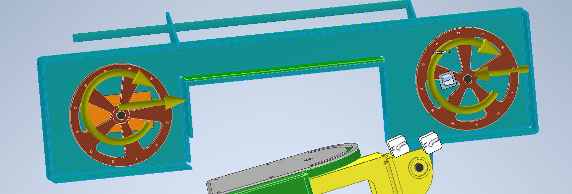
Hello! I'm attempting to run FEA on a bandsaw frame. I'm not really sure the forces involved, or how I should calculate them.
Firstly, I have my blade width - 0.75" 0.035". This is an effective cross section 0.02625 in2. Times 25,000psi, gives a load of ~650 lbs. Lest just round up to 700.
So now on to applying that load to the model..
1. Bearing loads of 700lbs at each axle, in opposing directions.
2. Moment loads of 700ft lbs(wheel diameter is 12 inch), at each wheel.
3. Applied constraints to the head assy. pivot point.
I'm not sure if I'm applying the correct forces in the correct amounts/locations. Furthermore, I'm not sure if this amount of deflection is acceptable or not. I could always go to a smaller blade, or add more material supports to the frame(not sure where the best location would even be). Would deeply appreciate some guidance on the matter!

Accepted answer

Hello!
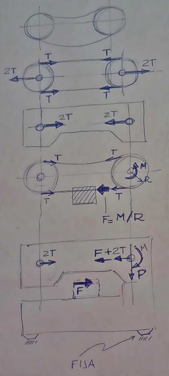
The first thing you must be clear about is which piece or set of pieces you want to verify and make a suitable "free body diagram".
For example, if you are interested in the frame of the tape, you must isolate it and replace the parts that were in contact with it by the actions they exert on it.
If you isolate the frame, you will replace "the floor" it rests on with a boundary condition that could be a fixed surface.
You will also replace the saw and its pulleys (and bearings) with a set of forces: one of them is the mounting tension of the pulley "T" and another is the additional force for the cut "F".
Tension T is in both legs of the saw, so what the frame sees is a force equal to 2*T in each of its bearing supports.
The additional force for cutting comes from the torque exerted by the motor (which you will also be eliminating in this free body diagram). This cutting force "F" occurs on the lower leg of the saw, between the drive pulley and the piece you are cutting. The part that acts on the drive pulley is transferred to the frame on the drive bearing support. And the part that acts on the piece, is downloaded in the support of said piece on the frame.
The motor action (torque) "M" is dumped onto the frame, perhaps into some flange bolts on the front of the motor, or a base flange. In any case, the weight "P" of the motor is discharged on the frame in the same way (in the place where it is supported or supported).
With this scheme (FBD Free Body Diagram) you can place all the boundary conditions (forces and supports) to verify your part.
Hope this can help you.
Greetings
PS: Of course, if relevant, you can add the self weight of the frame at its center of gravity.
PS2: to understand the directions adopted by the forces, you have to take into account that "what appears on a piece" is the action that the other piece does on it. The pulley pulls the saw and vice versa, the saw pulls the pulley. So if you make a BFD of the saw, you will have to place the force that the pulley does to it. And if you do a FBD of the pulley, you will put the same force in the reverse direction (which is what the saw does to the pulley).