

3D Printing: Tip Selection FDM Best Practices

To minimize build time and ensure feature details are built, it is important to select the correct tip size for each part. Using too small a tip on a part can significantly increase build times. Example: a part with a 5” z-axis dimension will have 500 layers using a T16 tip, 715 layers using a T12 tip, and 1000 layers using a T10 tip.
The following tutorial is brought to you by Stratasys.
-
Step 1: Determining Part Size
Determine the size of the part; x, y, and z dimensions. Remember that Insight displays measurement information in the bottom-right corner. General rule of thumb is:
• Parts 6” or larger use T16 tip
• Parts 3-6” use T12 tip
• Parts 3” or smaller use T10 tip
• Measure Wall thickness, boss diameters, etc.
-
Step 2: Width Measurements
By measuring the smallest part features in Insight, such as wall thickness, boss diameters, and other features road-widths can be determined.
A. View Road-width measurements in Insight by right-clicking in the graphics window and selecting Measure (figure 1) go to Toolpaths>Setup and look at the drop-down menu for both contours and rasters (see figure 2). This is important because this allows use of a larger tip and fills in feature details down to 0.016”. By using the larger tip and modifying the road-widths only where necessary, decreases build time considerably. Road-widths can be modified on a layer-by-layer basis using the Custom Groups tool in Insight (reference the Insight User Guide).


B. Measure Data by Selecting View on the main toolbar and selecting Measure Data to view data.
-
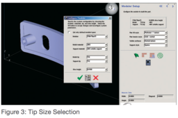
Step 3: Tip Selection
Tip size selection is done prior to processing the part and after the STL has been loaded into Insight. Choose the tip size after you have selected the material. Remember, some materials have a limited tip selection. PPSF, for example, uses only T16 tips. Tip size selection is done from the Modeler Setup screen in Insight (figure 3).

