

Best Practices for Modeling Castings in SOLIDWORKS

Casting covers a variety of parts and is useful in many industries from creating highly stylized claws to standard automotive parts. In this tutorial, one of our Elite Application Engineers shows his tips and tricks for modeling castings.
-
Step 1: As Cast/Make From
Key SOLIDWORKS Technology:
o Configurations
o Suppress
o Delete Face
o Move Face
Key SOLIDWORKS Benefits:
o Short path to multiple deliverables
o Flexible modeling approach

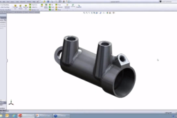
The actuator was originally an aluminum casting. This configuration shows what the cast's appearance should be. There are missing ports and bores in the back, and an additional difference is the design of the cast, which has a spherical radius and a cone-shaped piece. There are two versions because the actuator was mounted differently in each version. One actuator was mounted at a 27º angle and the other at about 12º. In order to get a casting, it is done with configurations that you see over on the third tab over the Property Manager which allows you to save different versions of the same part. The feature tree shows how the entire part was created.
The default configuration (PO1) is showing. You can walk through how it was created by adding components and trimming them in. There is a subtle difference between the two features anticipating the desire to make a casting later. The original part was built a little bit too big, and then another cut was created to trim them back to the actual design requirements of where the faces needed to be.
-
Step 2: Adding Another Casting
To add another casting, make a new configuration (named JDP casting). Take those features that represent the cuts and suppress them, and they will get turned off from the tree. You can also suppress a machine face feature.
If you are a little bit off or need to get rid of some other features, you can go into direct editing tools. One is called Move Face. This allows you to pick any face in SOLIDWORKS and simply define it offset, slide it through space and translate it left or right. The main difference is if you pick something cylindrical or you might take a face and move it one way or another.

You can offset and add on extra material if needed. To make the casting apply smoother, you can put fillets on it as well.
By moving the face and putting on additional features or in different cuts, you can generate the cast.
You can go back to Default and see that the Move Face feature and the fillet feature are suppressed. You won’t see those in the production part. They will only show up in the casting configuration. On an alternate configuration, you can take a dimension and make a change to it so that it will have a difference value only in this configuration.
All your different designs will be documented at the same time (in the same part file) and the drawings fall out from here if you need to define that casting as its own controlled drawing. You have the geometry for that as well as any of the final machine pieces that you need to show.
Delete Face is another way that you can remove some geometry. Go into Direct Editing and choose Delete Face. That will allow you to remove some faces from the solid model and SOLIDWORKS will automatically patch and repair the remaining faces that are left over.
-
Step 3: Pattern Making
Key SOLIDWORKS Technology:
o Multibody Parts
o Save Bodies
o Combine

This is the final produced part. To understand the design process, it helps to go back to the beginning where there are several different sketches.

This shows the inside and outside contours of the space. Often with castings, you are designing around negative space. This shows where the gears need to go and where the body of this housing is going to go. Then, you must decide where the screw bosses need to go to bolt this to its main part. You can design some curves along the side to give it attractive contouring and then a bridge across the middle for added rigidity and to make room for some other components.
From that, you extract your different pieces of sketch geometry. You can start with the pattern on the inside. The shape is a combination of pulling out these different circles from the screw bosses and the inside edge of the thickness of our housing. There are a couple of extra lines and a little bit of trimming which give you this shape. You build up how tall the housing needs to be. This core needs to be built and fabricated out of its own patterns somewhere else and needs to incorporate the right draft angles. Add some fillets and cuts to get the rest of the contouring, offsetting from those design cues, making a couple of cuts to make room for the bridge that will go in the middle and some fillets to round it off.

You can take this resulting shape and use a command called Save Bodies, which allows you to take the solid body and push it out into its own part file. SOLIDWORKS puts a place holder in the Feature Tree to show that you have done that and allows you to come back and find out what the name of that part was and where it was saved.
To build the outside of the gear box, you use a similar approach by gathering different sketches, using convert entities and trim, cutting away the shape of the bridge you need and putting some fillets on to create the outside of the pattern.

Once again, using the Save Bodies tool, you can put it into a separate file.
You have designed the inside and outside features in parallel. You have two different saved bodies which you can combine. It allows you to take the two bodies and subtract one from the other so that you can subtract the core from the cavity.

You still need to put on some machine features. You can go and generate the drawing with all the details for the machine features. All three paths are captured in one single file. This process is more straightforward than using configurations.
Key SOLIDWORKS benefits:
o Design as you go
o Automatic capture of production needs
-
Step 4: Pattern Trees
Key SOLIDWORKS technology:
o Component Pattern
o Edit Subassembly
o Move/Rotate Component
Using a golf club as an example, take the part and drop it into assembly. Make a pattern to build up what your tree is going to look like. Go and generate an axis and make a pattern. Use the axis to pattern around, and that will be the center of the tree. The component you want to capture is the golf club. Click on the part (which is fixed). Right-click and choose Float. That will allow you to grab the part and drag it around in space. This allows you to visualize what the ideal arrangement of the parts will be because you can see when they are going to bump into each other. You can span them in and out and rotate them.


Now you can adjust these. You can edit the subassembly and are able to rotate the parts to determine if there is a better arrangement. If you want to do another pattern, you can add another assembly to this. From there you can take 3d measurements and angles to figure out exactly where it is going to go and what angles need to be used to help with any registration or to build some guides and templates for arranging the patterns in real life.

Watch the full tutorial video here
