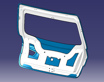
Back door design and Engineering Feature


This project aims to design a sheet metal panel for a car's backdoor using provided skin data while adhering to design rules and guidelines. The backdoor serves various functions, including rear coverage, visibility, and storage. The design process involves selecting the backdoor type (top-mounted, side-mounted, or bottom-mounted), choosing materials (steel or aluminum), and creating components like outer and inner panels, hinges, and reinforcements. The design is based on factors like rear visibility, sealing, structural support, crash regulations, and joining techniques. The outcome is a well-designed backdoor assembly that considers both functionality and aesthetics.
-
Step 1: Design Procedure
Styling Surface Clean-up: Before creating the CAD model, it is crucial to check the given styling surface for any discontinuities or inconsistencies. The surface continuity is examined to ensure that the distance between the surfaces is within the acceptable tolerance limit (usually less than 0.0001 mm).
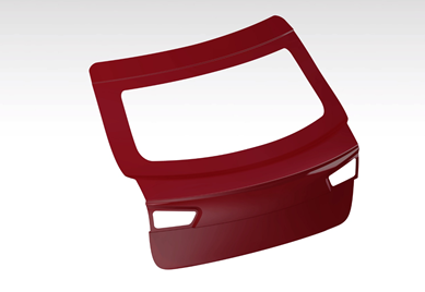
Outer Panel: The outer panel serves as the outer styling skin surface of the backdoor. It is coated with multistage coatings that provide properties such as scratch resistance and rust prevention. The outer panel is wrapped around the inner panel using a hemming process.
Inner Panel: The inner panel is a vital component of the backdoor assembly. It provides structural strength and assists in dissipating external forces through strategically placed embosses. The inner panel also facilitates the mounting of various accessories, including hinges, wiper motor, gas stay, latch, and striker.
Casting or Deep Drawing: The inner panel can be produced either through casting or deep drawing processes, depending on the material used. Aluminum parts are often casted, while steel inner panels are typically manufactured using the deep drawing process. In the case of deep drawing, a specific tooling direction is required to achieve the desired shape and dimensions of the panel.
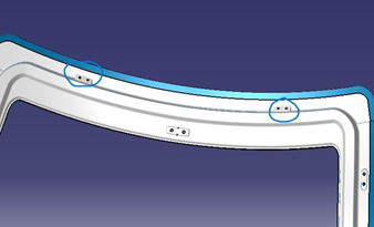
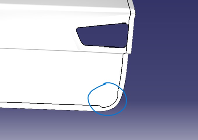
Corner Relief:
During the hemming process, the use of multiple rollers can result in vibrations and stress concentrations at certain locations, particularly at the corners. These conditions can affect the design intent of the panel, as the desired outcome is for the panel to spring back to its original formation once the roller is removed. However, corners often do not behave in the same manner, and the panel may not return to its intended shape.
-
Step 2: Design considerations:
- Rear visibility
- Boot space & accessibility
- Sealing Flange
- Support structures like hinges and gas stays.
- Mounts for wiper motor, tail lamps and other wiring loops
- Rear crash regulations
- Joining techniques such as hemming, spot welding etc.
- Gap and flush requirements
-
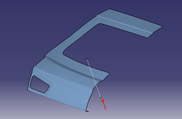
Step 3: Class A surface

Creation of class A surface from the styling surface
-
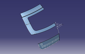
Step 4: Creation of tooling axis
First, we need to create the Tooling direction for the Deep drawing operation. It shows that all the operations like embossing are done by considering this vector direction and it will help in manufacturing the part,
-
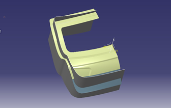
Step 5: Design of inner panel
Then we will be creating the Back door inner panel flange by offsetting the outer surface at a distance considering the sheet thickness and thickening direction.
Then created the connecting flange to join the inner panel and sealing flange.
Then for the windshield panel mounting, the windshield panel is created and joined with a sealing flange.
Offset the class A surface downward direction. To perform Hemming, offset the present surface to 0.95mm (inner Surface Thickness- 0.75mm, Inner panel thickness- 0.75 gap between Outer and Inner panel – 0.2mm, Hemming area bent region- 0.75mm, the gap between hem and Inner panel- 0.2mm)
Use the parallel curve option to 10mm to create the surface.
-
 Using the sweep command sweep the parallel curve with the tooling direction.
Using the split command split the offset surface.

- Now, use the offset of 1.7 to trim the sweep and creating a surface.
- After creating the boundary surface of the inner surface, extract the windshield area and extract it.
- Now create a sweep inside with an angle of 25 degrees and trim it with windshield extract.

The inner panel base surface is complete. The next step is creating the embosses, Gas stay mount, Hinges mount, Sticker mount, creating mastic data and wiper motor mount

-
-
Step 6: Engineering Features
Hinges support mount
Gas stay mount

Wiper motor mount

Embosses
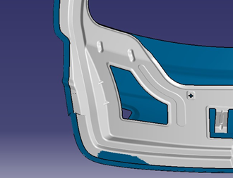
Mastic data region
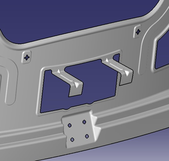
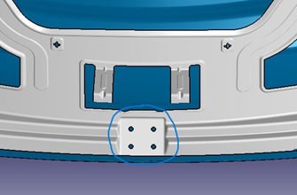
Sticker mount
Hemming and corner relief
-
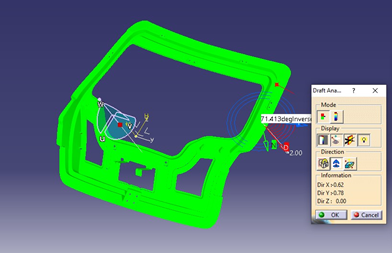
Step 7: Draft Analysis
Draft analysis of inner pannel
-
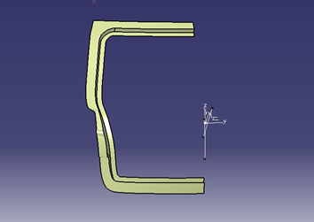
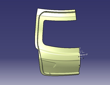
Step 8: Back door parts
Outer panel:
Inner panel:


Assembly of the outer panel and inner panel: