

Car roof components design and analysis


To achieve an efficient and well-engineered car roof design, various critical considerations are taken into account. This article explores the aim and objectives of designing and developing a car roof, along with essential factors such as visibility, heat distortion, snow load criteria, and draft analysis. Additionally, the role of roof components, like the front and rear roof rails, reinforcement center, and bow roofs, is examined in enhancing the overall strength and performance of the car's roof. By meticulously analyzing these design parameters, engineers and designers can create a robust and aesthetically appealing car roof that meets stringent safety standards and fulfills customer expectations.
-
Step 1: Introduction to car roof
Roof: The roof of an automobile, also known as the car top, is the uppermost part of the vehicle that is situated above the passenger compartment. Its primary purpose is to shield the occupants from external elements such as the sun, wind, rain, and other weather conditions.

Design consideration of roof:
· Visibility Criteria
· Head clearance
· Curvature study
· Heat distortion and snow load criteria
· Draft analysis.
· Safety parameters
-
Step 2: Design consideration of car roof support structure
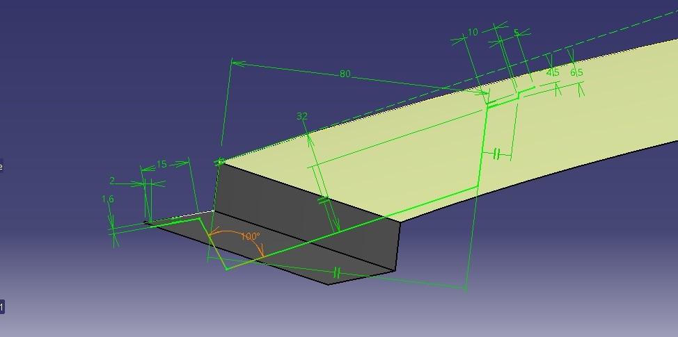
·Front Roof Rail: The front roof rail serves as an additional component that reinforces the roof structure. It includes various features such as supporting brackets for map lamps and room lamps, enhancing functionality and convenience.
Sheet metal thickness: T= 0.75 m
Emboss height: 2 < 3
Flange length: 13.2 > 3T+R
Radius: (R=3mm and 5mmm )> T
Rear Roof Rail: The rear roof rail primarily supports the roof of the car. It also assists in the operation of the back door hinges, facilitating smooth opening and closing.
The following points are considered
Headroom clearance: 120mm minimum
Sheet metal thickness: T= 0.75mm
Emboss height: 2 < 3T
Radius: (R=3mm and 5mmm )> T
Reinforcement Center: The reinforcement center is a crucial structural element of the roof. It acts as the primary support member, absorbing energy during side impacts or crashes. In smaller cars, it also functions as a bow roof, providing additional strength and rigidity.

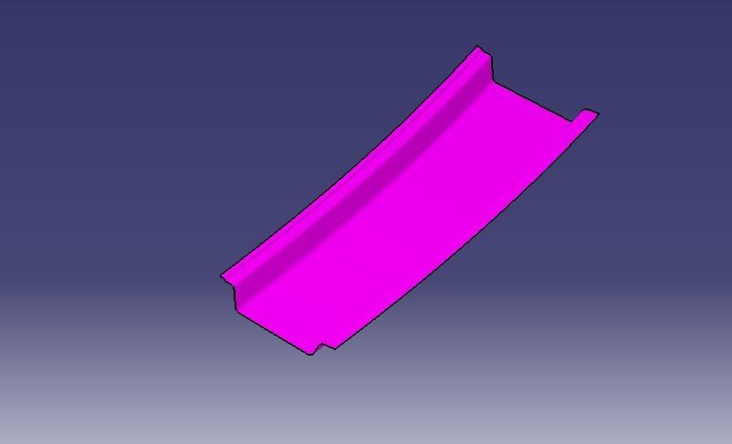
Bow Roofs: Bow roofs are roof-supporting rails designed to enhance the overall stiffness and structural integrity of the vehicle's roof. They are engineered based on specific criteria such as heat distortion and snow load conditions to ensure optimal performance and safety.
-
Step 3: Master Section

-
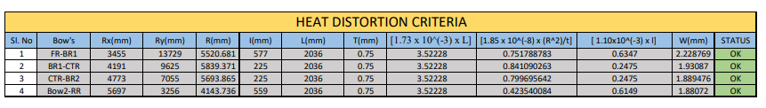
Step 4: Heat Distortion Criteria
Heat distortion criteria:
Heat distortion criteria are used to determine the temperature at which materials begin to "soften" or deform when subjected to a specific load under elevated temperatures, caused by the heat radiating from the sun. In the context of a car's roof, these criteria help identify the temperature threshold at which the metallic regions of the roof may undergo changes due to heat exposure.
W = [1.73 x 10^(-3) x L] + [1.85 x 10^(-8) x (R^2)/t] + [ 1.10x10^(-3) x l] - 2.6
Where,
L = Roof Length in X-Direction[mm](Roof dimension in 0-Y)
R = Roof curvature
R = 2(Rx*Ry)/(Rx+Ry)
Rx = X curvature
Ry = Y curvature
t = Roof plate thickness [mm]
l = Bow Roof Span [mm]
Judgment Condition: OK< 2.7mm
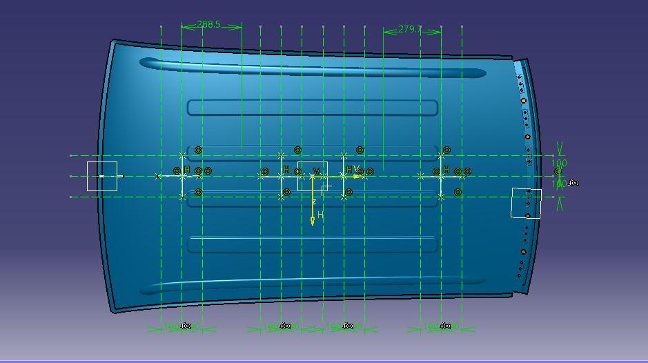
Finding Rx and Ry curvature:
Create a line between the support structure the offset that line by 100mm on both sides. Mark the intersection point.

Project a marked point on the top roof surface then join the points by using the spline command to measure the radius of the curvature.

RESULT OF HEAT DISTORTION CRITERIA:
-
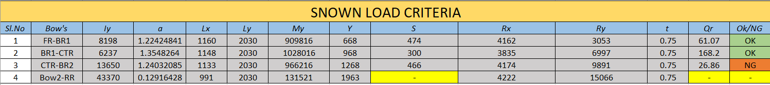
Step 5: Snow Load Criteria
Snow load criteria:
Snow load criteria are essential for determining the maximum amount of snow weight that a car's roof can withstand without failure. During the winter season, snow can accumulate on the top surface or roof of a car, exerting a significant mass. If the weight of the snow load exceeds the design capacity of the roof, it can lead to structural failure or damage. By considering snow load criteria, engineers and designers can ensure that the roof is constructed to safely support the expected weight of snow during winter conditions.
Where,
α = My x Lx2 x 10-12 , My = Y(Ly-Y)
t = Roof plate thickness [mm]
Ly = Distance between the front and rear roof Rails on the Vehicle along with 0Y[mm]
Length of Roof panel with the center point between Roof rail Front /Rear as the reference point of the front and the rear.
Lx = Distance between the Left and Right end of the roof on the Roof BOW [mm]
Width of the roof panel exposed on the surface.
Y = Distance from front Roof Rail to Roof BOW[mm]
s = Distance for which Roof BOW bears divided load [mm]
s = L1/2 + L2/2
Iy = Geometrical moment of inertia of Roof BOW (Y cross-section) [mm4]
Rx = Lateral direction curvature radius of roof panel Y cross-section on Roof BOW [mm] Roof panel curvature Radius of the Length Lx in Front view
Ry = Longitudinal Direction curvature radius of the Roof Panel X cross-section on Roof BOW [mm]
Roof panel X curvature radius of length s in Side view
Judgement condition = Qr ≥ 3.1
250 ≤ s ≤ 380
Rx & Ry (X & Y Curvature):
At the 0-Y axis on a perpendicular plane to the roof, as shown in fig. draw 100 mm lines offset to either side of the 0Y axis line. Now center lines are drawn between each adjacent roof rail edge respectively. Intersection points are marked on the sketch and exit the sketch. Make all geometry in construction lines except the points.
Project the intersection points in the sketch to the roof surface as shown in Fig.
Join the projected curves using an arc curve and measure the minimum radius and linear dimension.
Project the intersection plane bow roof and center roof rail on the horizontal plane to find the moment of inertia of the respective section to find Iy values.
Put all the linear and radial dimensions in the following formula to calculate Qr Value.
From the above fig, now project the points on the top of the Roof and draw the arc with the three points intersecting area as shown in below fig,

Result,
-
Step 6: Draft Analysis
Bow roof:

Inner front roof rail:

Inner rear roof rail:

Rear roof rail:

Outer panel:

-
Step 7: Roof Assembly

Front view:

Side view:

