

Curl Management Using Insight

Curl is defined as the distortion of horizontal surfaces caused by the shrinkage of a new layer as it’s applied over the existing layers, causing those layers to deform. This can be a challenge with parts that have thick cross sections or large at areas. InsightTM software features several tools that can mitigate part curl even on the most challenging geometries.
-
Step 1: Options
Base Layer Modifications
Two non-invasive ways to reduce part curl are to increase the support Base oversize and Base layers values in the Insight software Support Parameters dialog box. Change one or both values as needed to achieve the best results. These two options are ideal when used with standard and engineering-grade thermoplastics because they won’t leave any residual marks on the part.
Removing Perforations
For materials with breakaway supports the default support parameters add perforations (single model layers incorporated in the support at predetermined intervals) for ease of support removal. For geometries where a large amount of stress may induce curling, failure may occur at the perforation layer. Typically, these geometries have large areas of support and curling can be avoided by eliminating perforations.
Anchor Columns
On large at parts (> 305 mm [12 in.] long and >12.7 mm [0.5 in.] thick) that have the potential to curl due to differential cooling, anchor columns may be used to secure the model to the base. The anchor column is made of model material and will need to be mechanically removed after the build. Placement and quantity will depend on the part’s geometry and any observed curl in previous builds.
Anchor Profiles
Anchor profiles offer the advantage of anchoring the part in a uniform manner around its perimeter. This manual process is typically used when anchor columns aren’t sufficient to secure the part.
-
Step 2: Software and Materials
Software:
Insight software
Control Center software
Materials:
All Fortus Materials
-
Step 3: Base Layer Modifications
STEP A: From the Support menu, select Setup
STEP B: Click to access the Support Parameters
STEP C: In the Base section, make sure the checkbox next to Contour Base is checked (Figure 1)

STEP D: In the Base section, increase the value in the Base oversize field
STEP E: In the Base section, increase the value in the Base Layers field to add additional layers
STEP F: Click the green check mark to confirm the change
STEP G: This completes the base layer modification procedure
-
Step 4: Removing Perforations (Large Areas of Support)
STEP A: From the Support menu, select Setup
STEP B: Click to access the Support Parameters
STEP C In the Perforation section, clear the checkbox next to Interval height to remove all perforations (Figure 2)

STEP D: Click the green check mark to confirm the change
STEP E: This completes the procedure to remove perforations
-
Step 5: Anchor Columns
STEP A: From the Support menu, select Anchor column
STEP B: Specify the desired Top diameter and Bottom diameter
STEP C: Find the bottom layer of the part feature that will be secured using the anchor column. The next step is best done from a top-down view.
STEP D: Position the cursor on the location where you want to put the anchor column and left click. The center point of the selected location will populate (Figure 4).

STEP E: Click OK to confirm the anchor column location
STEP F: Repeat the procedure to place any additional anchor columns.
STEP G: This completes the procedure for creating anchor columns.
-
Step 6: Anchor Profiles
STEP A: Configure the modeler
STEP B: Click and orient the STL
STEP C: Click to create part curves using the current parameters
STEP D: From the Support menu, select Setup
STEP E: Click to access the Support Parameters
STEP F: In the Support to create section, select Supports extended for base. In the Base section, make sure the checkbox next to Contour base is checked and change the Base oversize to 0.00000 (Figure 5)

STEP G: Click to create supports for the current job
STEP H: From the Edit menu, select Copy Curves Through Z to extend the outer perimeter model contour down to the build sheet. Change the Copy mode to Specify through Z coordinate. Enter the desired value into the Through Z height field (in this case: -0.0400). Change the Destination group to Same as selected (Figure 6).

STEP I: From the Edit menu, select Offset Curves to offset the outer perimeter model contour inward. Change the Offset direction to Inside closed curve. Enter the desired value into the Offset distance field (in this case: 0.0200). Change the Destination group to Same as selected. Change Keep original to Yes (Figure 7).

STEP J: From the Edit menu, select Copy Curves Through Z to extend the new inner perimeter model contour down to the build sheet. Change the Copy mode to Specify through Z coordinate. Specify the desired value into the Through Z height eld (in this case: -0.0400). Change the Destination group to Same as selected (Figure 8).

STEP K: From the Edit menu, select Offset Curves to offset all of the support contours that are outside of the outer perimeter model contour so that they are inside the new inner perimeter model contour. Change the Offset direction to Inside closed curve. Specify the desired value into the Offset distance field (in this case: 0.0700). Change the Destination group to Same as selected. Change Keep original to No (Figure 9).

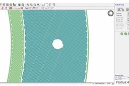
STEP L: Generate toolpaths (Figure 10).

STEP M: This completes the procedure for creating anchor profiles.
