Custom SOLIDWORKS ToolBox

How to custom hardware/hole wizard data for your company?
-
Step 1: Create a new Hole Wizard data
I have an example as following:
- You want to create custom screws similar ANSI B18.3.4M standard. You need a new counterbored size for your screws.
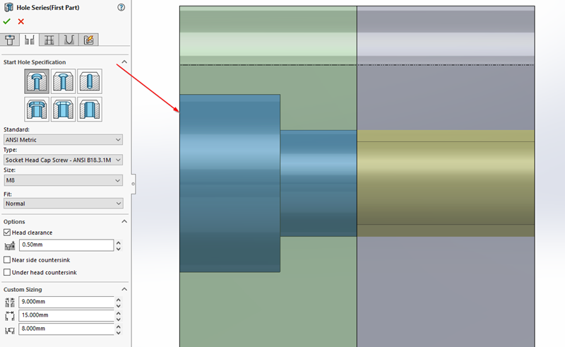
- In this example, you will create custom "Socket Buton Head Cap Screw" M1.6 and M3 type as below:


Now, you click to ANSI Metric > Choose Copy Standard > Enter your "Standard name" > click OK.

A new Hole Wizard data and Customize Hardware folder will be created as below:

and

-
Step 2: Add Sizes data in Hole Wizard data
There are 2x ways to add data:
- Use Import/Export Hole Data Tables to get/add data if there are many screws. (it's available in SOLIDWORKS 2018 or later).

- Click Plus icon to add New Size then you enter screw spec.

Before,

After,

--------------------------------------------------------------------------
Note:
(1) You can use Size name M3.0 or M3v1 to distinguish your data vs available data or you can edit to existed-M3 data if you want.

In this tutorial, you add some data to see some difference.
(2) The counterbored diameter/depth will be showed in the end of Feature Manager tree. You can modify here but it won't change data in Hole Wizard data.

(3) The Fit below Size is getting data from Screw Clearance table in Toolbox.

==========================================================
Explanation: The Socket Button Head Cap Screw has Hole Wizard parameters as below,
The Sizes table data include:

- Size and Diameter column: if the screw diameter is 3.0mm, you can add "M3.0" to this column, or other.
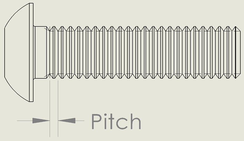
- Pitch and Threads Per Unit column: the pitch of thread, these columns value are similar.
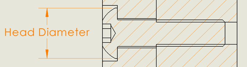
- Head Diameter: the head diameter of screw will use Hole Wizard data.
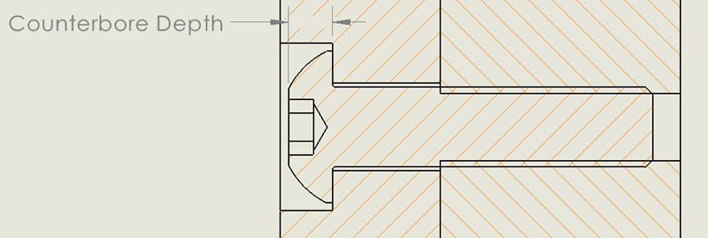
- Head Height and Counterbored Depth column: usually, we use counterbored depth equal to head height.
So, you add value to these columns similar.
The Counterbored Depth is showed and can be modified here.

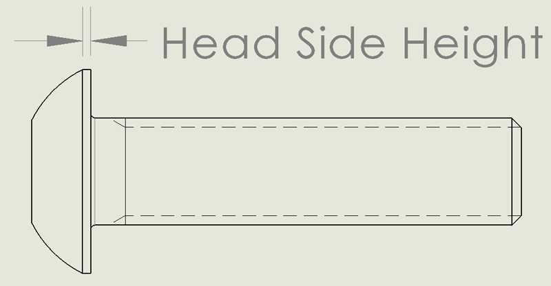
- Head Side Height:
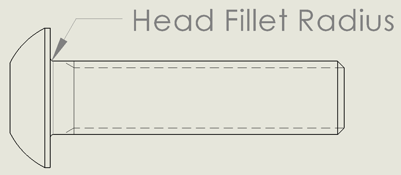
- Head Fillet Radius:
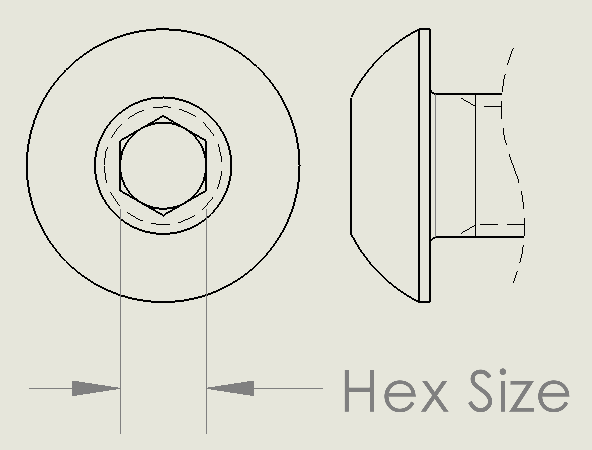
- Hex Size:
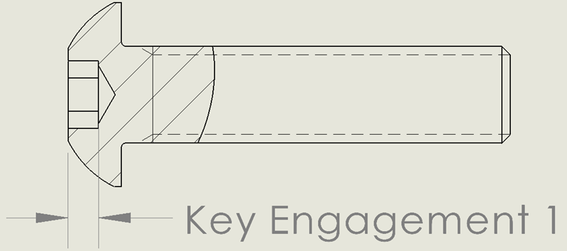
- Key Engagement 1:
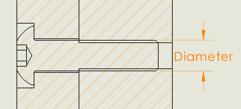
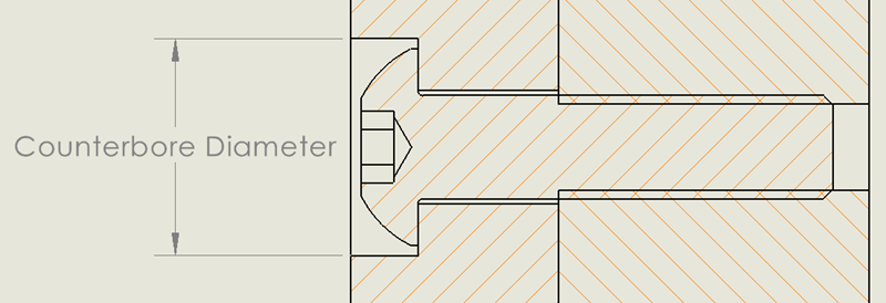
- Counterbore Diameter:
The Counterbored Diameter is showed and can be modified here.

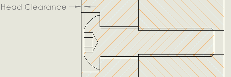
- Head Clearance: this is 0 as default. The head clearance will be setup in SOLIDWORKS environment. Example, it's 2.0mm

-
Step 3: Add Screw Clearance

After you added data into Size table data, you need also add close/normal/loose fit of hole if it's required.
Use Plus icon to add data into Screw Clearance table similar to Add Size data.
The Screw Clearance will be show in Fit item in FeatureManager tree.
Besides, it's shared data with other hole types like Screw Clearance of Straight Holes tables, etc...

Remember, click Save Toolbox after you added data.
===========================================
Explanation:
The Screw Clearance include:

- Size and Diameter: similar Size in Sizes table at step 2.

- Close Fit: min clearance.
- Normal Fit: normal clearance.
- Loose Fit: max clearance.
The Fit types are showed here:

-
Step 4: Add Thread Data
Now, we add New Thread Data for new holes.

Example, if we added M3x0.35 to Size table in Bottom Tapped Hole, we need add M3x0.35 thread data for this.
If not, the error will appear as below:

This property is shared with other holes. So, you will see M3x0.35 thread data in Thread Data table of other holes.
==========================================================
Explanation:
The Thread Data include:

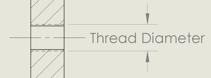
- Size and Thread Diameter column:
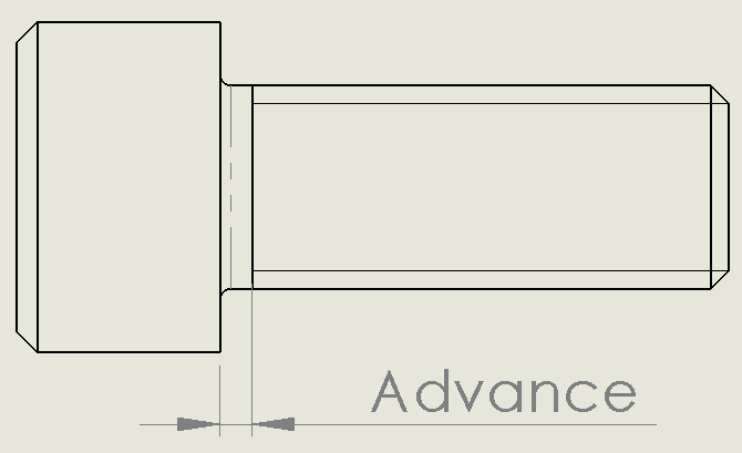
- Advance: Usually, it's equal to Pitch or Threads Per Unit:
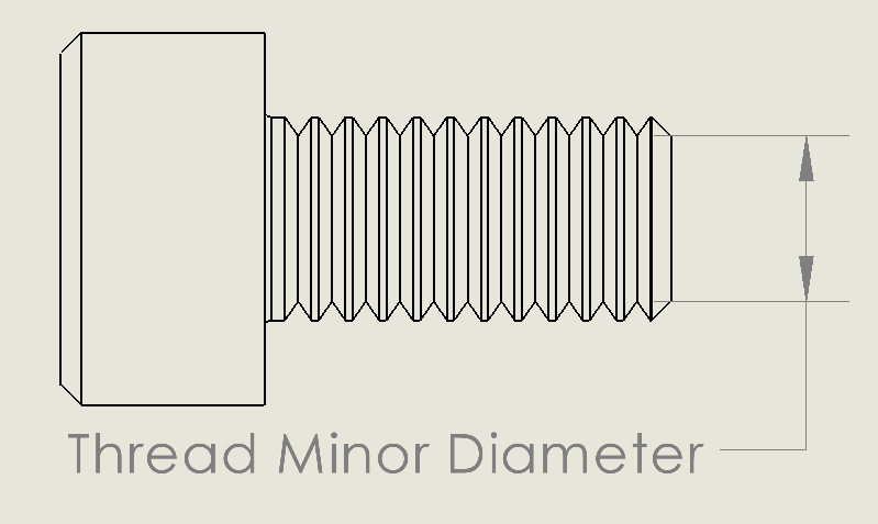
- Thread Minor Diameter: is the smallest diameter of an external thread.
- Thread Minor Diameter Inside: is the smallest diameter of an internal thread, like a NUT thread.
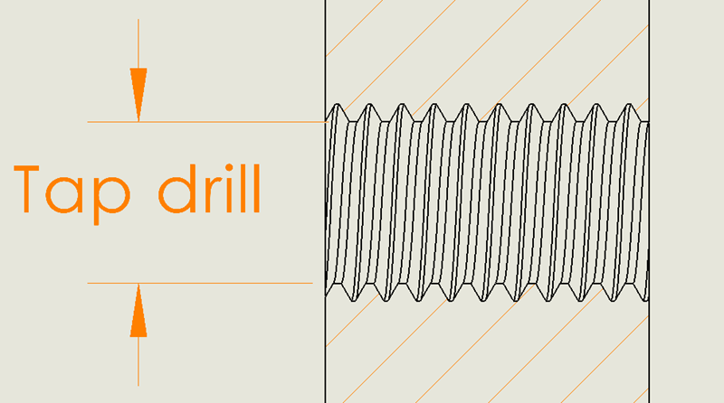
- Tap Drill: Basic or Nominal of Thread Minor Diameter Inside.
- Thread Description and full_size: M3x0.5, M3x0.35, for example.
- Series: can be empty.
Summary, you completed custom Hole Wizard data. Now, you can move to next step to create/update Hardware data in "Customize Hardware" tab.
-
Step 5: Customize Hardware

Now, we go to Toolbox tab 2 (Customize Hardware), in this, we add screw data corresponding to Hole Wizard data in previous steps.
(1) General property: tick "Allow custom configuration name" to modify "Configuration Name" column.

(2) Size property: click Plus icon to add new screw size or update in available data. This data is similar Size table in Hole Wizard data in previous steps.

(3) Length property: add new screws length.
Example, M2 has 3 length types, include 1.5mm, 2.0mm and 3.0mm, you need add them in this.

(4) Thread Display property: tick to use and untick to un-use.

(5) Thread Data property: you need add Thread Data for your screws, this is similar Thread Data in Hole Wizard data.

(6) Color: color for screw components.

NOTE: Every screw met a standard as DIN, ANSI, METRIC or ISO, etc,...
You should choose the right standard/screw type to create your custom screw/hole data. This is help you has fully parameters to add.
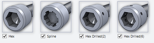
For other screw types, it has more some parameters like: Drive Types, Spline Size, or Hole location in Socket Head Cap Screw.
Drive Types:
1. If screws head use only Hex key, let's answer "HexOnly".
2. If it's Hex and Spline key, let's answer "HexAndSpline".
3. If it's Hex, Spline and 2x drilled holes key, let's answer "HexAndSplineAndDrilled2".
4. If Hex, spline and 6x drilled hole key, let's answer "HexAndSplineAndDrilled6".
5. If Hex and Drilled 6 positions key, let's answer "HexAndDrilled6".
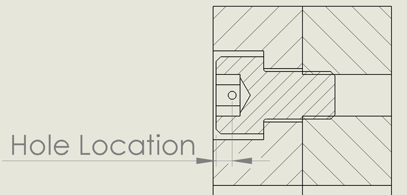
Hole Location:
Spline size (Normal Socket Size):
See Drive Types field for illustration.
You can refer "http://boltingspecialist.com/dimensions/asme-b18.3.1m-metric-socket-head-cap-screws" to get Normal Socket Size.
-
Step 6: Add Part Number, Description and comment

You click "Export data" to save screw data into excel file as below, then you add your part number, description and comment to that excel file.

Finally, you import your excel file to Toolbox, result as below: 

-
Step 7: User Setting
After you had all data for hole and screw, you need some setups in User Setting tab (the third tab in Toolbox).
You can use the Files, Writing to read-only documents and Part numbers as default.

Importance, if you want to use your part number and configuration name in FeatureManager tree and BOM, you need change options in Display options:
Change "Show as Component name in FeatureManager" to Part Number.
Change "Show as Part Number in Bill of Materials" to Part Number.
Finally, change "Show as Description in Bill of Material" to Description
The result like this.

-
Step 8: Permissions
You let set password and choose permissions here.

-
Step 9: Set up Smart Fasteners
Now, you can set up criteria for installing washer/fastener here.

Reference: Toolbox - Smart Fasteners - 2022 - SOLIDWORKS Help
=============================
Good luck!