

FreeCAD parametric 3d drawing

3D drawing driven by a data sheet. Example : creating a kitchen cabinet furniture driven by a Spreadsheet.
-
Step 1: Initialization
1) Create a new project
2) & 3) Select the "PART" Workbench
4) Save your new project

-
Step 2: Position the main part
The aim of this choose a part of your model wich will be the main symetrical part
1) Press the cube icon

2) Select axis cross visibility

As you can see the cube is not at a symetrical position, we will correct this later on.

Select the cube in the Tree Structure
1) Rename it
2) Change dimension approximatly for now just to get an idea of each dimension in front of each field (maybe the field "length" will be your real Width or Height. You can not rename these fields, just consider them as abstract fields name)

-
Step 3: Parametric Cube
The aim of this step is to create fields dimension in a SpreadSheet (wich is a sort of Excel sheet embed in Freecad with wich you can pilot your data)
Select the "SPREADSHEET" menu in the selector

Create a new Spreadsheet

Double-Click on Spreadsheet in the tree structure

Enter your field description by just typing in the text as you would do with an Excel or Libre office Calc sheet
The only difference is that you have to press enter, just leaving the cell to another one will not save it (at first you will have to get use to this)
Note that this description will only be a label, you can make it long and descriptive, it will not be used in the formula calculator

Type in "=425" or wathever the dimension are
Note that I am putting this information just next to the Label, once again, I had no need for a label, or putting this information in this particular cell, this is just a way of making the sheet easy to read for further uses.

1) Select the first Cell
2) Then click on "SET ALIAS" (you can also access the alias name of this cell with de rightclic + property)

Select an official short name (without space) of this field, it will be this field we will use in formulas, better make it short and explicit.
For example Dep_Low_Pan

As you proceed with every field, the cells will become YELLOW
If you go over the cell without moving or clicking the name of the field will appear, you can always change whatever you want : name of the field or value.

These fields are not related yet to anything in our 3D
We will proceed to this link in the next step
-
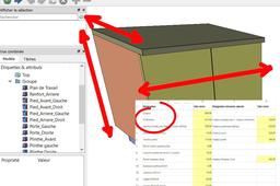
Step 4: Linking SpreadSheet to 3D model
Clic just once on the part "cube" That you have renamed so that the fields of this part appears.
If you have accidently left the spreadsheet because you clicked too strongly, just get back to it using the TAB in the bottom

Go to the first field of the box and click on it
A tiny yet powerfull icon will appear, click on it

The Formula Editor will permit us to link anything with anything just using simple formulas.
Just start typing in the beginning of the word "Spreadsheet" and the correct beginning of the path we are looking for will appear.

Choose Spreadsheet
Then we must add the name of the correct field we just created
For this ewample the "LENGTH" of the Cube is the Length of the low pannel.
Begin typing in the name of this field we created ("Len_Low_Pan") and this field will appear in the dropdown list.
NOTE that the name is CASE SENSITIVE
Select it

As soon as we enter the correct path with the correct field we created, the Formula Editor finds the value we just wrote

Click OK and you will see that the value is correct and is linked to the SpreadSheet
You can go on like this with all three fields

-
Step 5: Changing values
Changing the value in the SpreadSheet will change the 3D


-
Step 6: Position the model
You might want to position your model according to specific calculation.
That is usefull if you want to put your model in the middle so you can easely use symetric function.
Professional 3d always want to have an object centered.
You have 2 ways of doing this.
You can make the calculation inside the formula editor using various operation.

Soon you will realise that you loose the all picture of these calculations !
Or you can make these calculation in the SpreadSheet
The second option is easyer because you can correct these figure more quickly.
Lets explore the second way
Create in the sheet a second aera that will use the primary data you have entered

Create the operation simply
Note that you will not need to use the path SPREADSHEET because you are already in it.

For the center I let you bet what will be the formula

Dont forget to put the minus sign because we want the 3d to be centered, so it needs to scroll back to the middle of it's length
Now that you have made these calculation you must give them a FIELD NAME
Use the ALIAS name creator as you already did
(I named my fields CenterX, CenterY and CenterZ these are my choice, you could have chosen other names)

Then use these fields in the BASE /PLACEMENT/ POSITION

Now you will see that the 3D is centered

-
Step 7: Playing with an example
Please feel free to download and try my parametric cabinet model

Thank you for reading my first tutorial
