

How to create this part in CATIA V5

Tutorial ready.
-
Step 1:
Step1- Open new part and go generative shape design. Create sketch at XY plane and draw the same on picture.

-
Step 2:
Step2- Create a new plane with offset from XY plane with value 120mm.

-
Step 3:
Step3- Create new sketch to Plane.1 and draw the circle.

-
Step 4:
Step4- Create new sketch to YZ plane and project sketch.1(rectangle) and make projected line construction/reference element. And create a point on the right end of projected line. (marked with red elips)

-
Step 5:
Step5- Create new sketch to YZ plane and project sketch.2(circle) and make projected line construction/reference element. And create a point on the right end of projected line. (marked with red elips)

-
Step 6:
Step6- You will reach the these sketches which seen on picture.

-
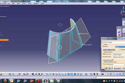
Step 7:
Step7- Run multi-sections surface command and select sketch1. and sketch2 as a sections. Then relocate the closing points by right clicking them and selecting replace selection. then check the red arrow direction. next go to coupling tab and select Ratio. Complete multi-sections surface.

-
Step 8:
Step8- Run split command and divide multi-section surface with ZX plane.

-
Step 9:
Step9- Go: Start-->Mechanical Design--> Generative Sheetmetal Design.
Set the sheet metal parameters as shown.
-
Step 10:
Step10- Run Hopper command and select split surface as a selection.
Part completed.

