

Modeling screw and nut threads for 3D printing using Fusion 360


Using a simple example of a screw and nut assembly with metric threads, we will explain the basic modeling procedure and necessary adjustments for printing a functional thread.
The example will focus on creating an M10 metric thread, however, steps 1 to 8 explain how to create basic geometry without much detail, in order to provide sufficient context for understanding the general procedure for modeling a thread. This procedure can be extrapolated to other types of threads (not necessarily metric), including a custom thread created by the designer.
If you already know how to model threads, I recommend going directly to step 9 to learn about the necessary adjustments to achieve functional printed threads.
It is important to keep in mind that this procedure and the printing of screws and nuts in general is limited by the dimensions of the thread. That is, if it is too small, the results may be deficient or difficult to achieve. For example, an M3 thread may be almost impossible to achieve, but an M8 or M9 thread becomes easier to print.
I hope you find this tutorial useful.
-
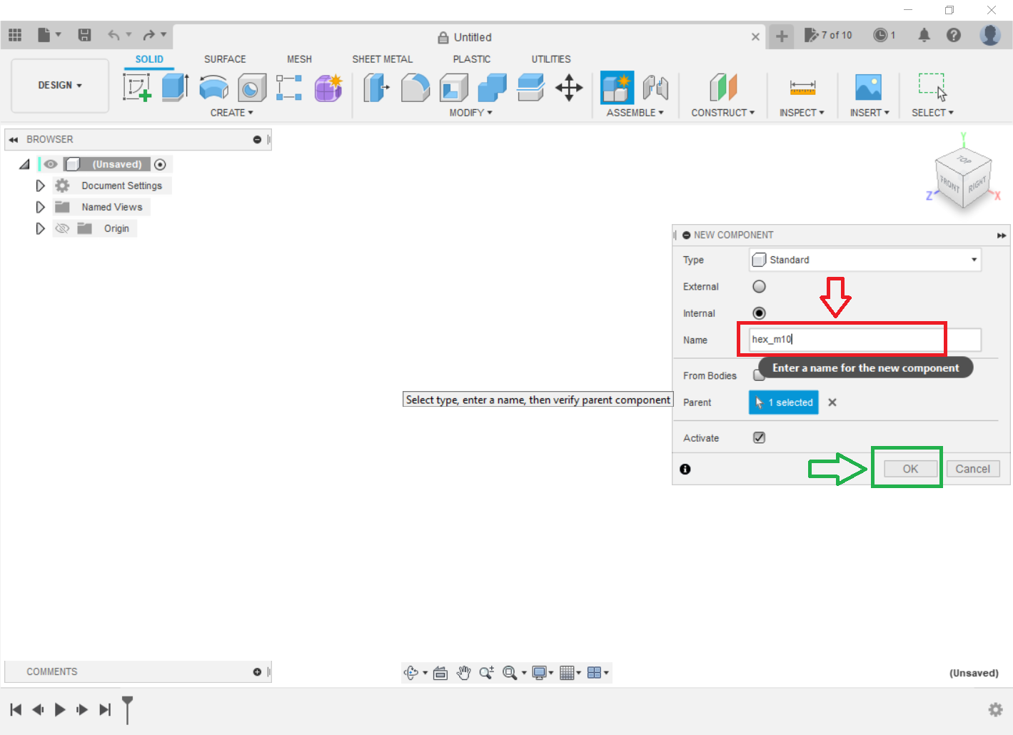
Step 1: Create a component
Go to create a select "New Component".
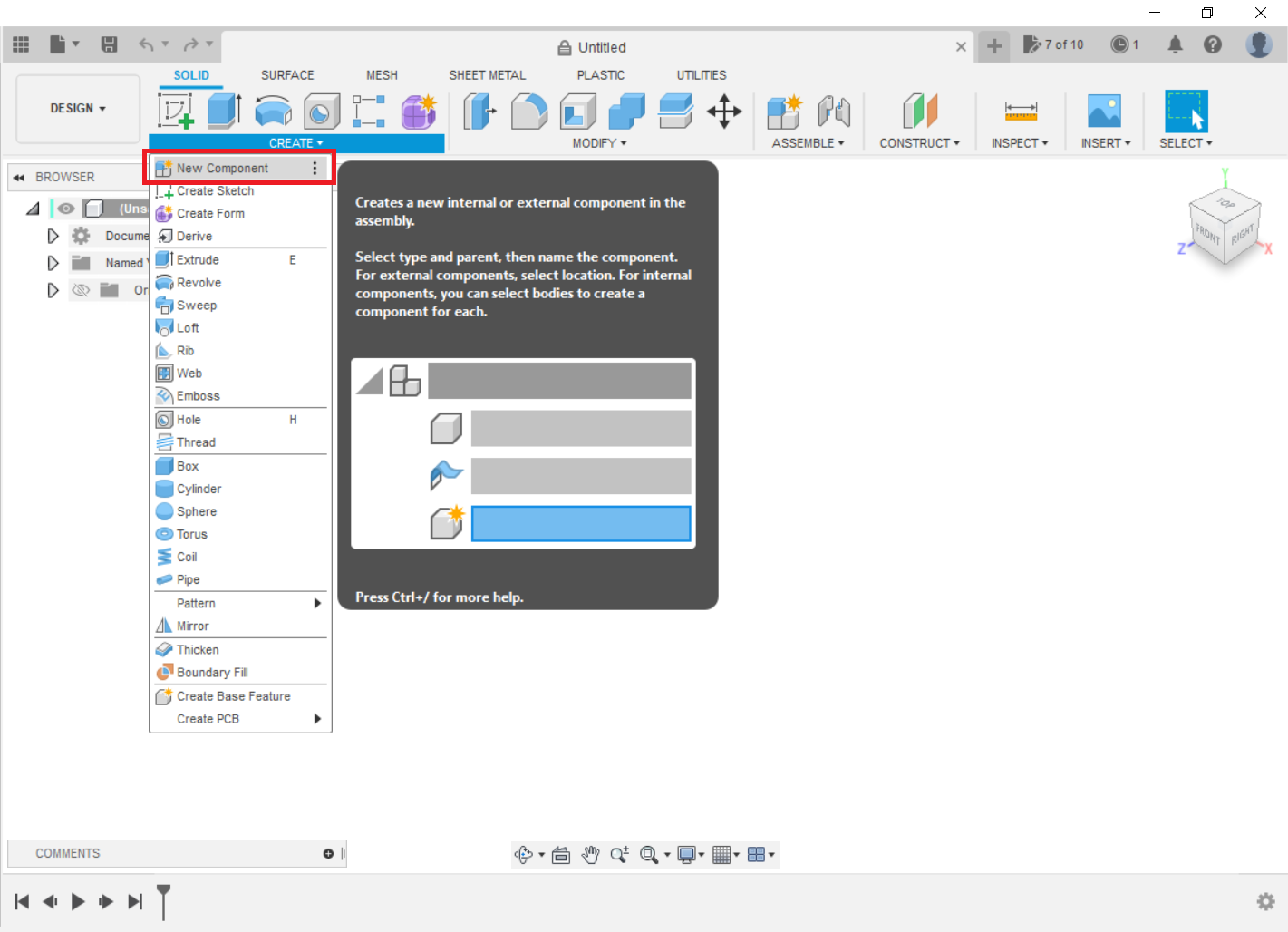
I called it this way, but you can use any name you like. Press OK.
-
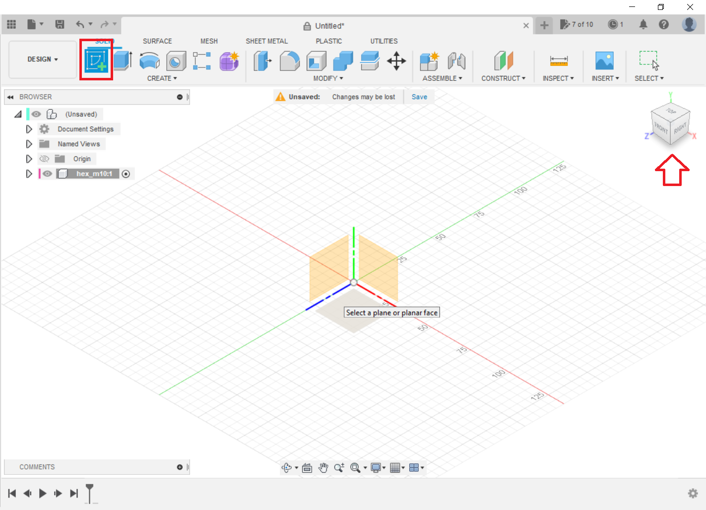
Step 2: Create a sketch
I used the XZ plane, as it seems to be a favorable default position for viewing and editing the model.
-
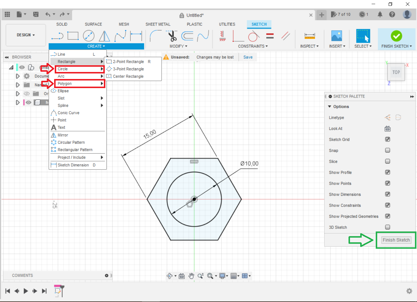
Step 3: Draw a circle and a hexagon.
Draw a circle and a hexagon using the displayed dimensions, and then press Finish Sketch.
-
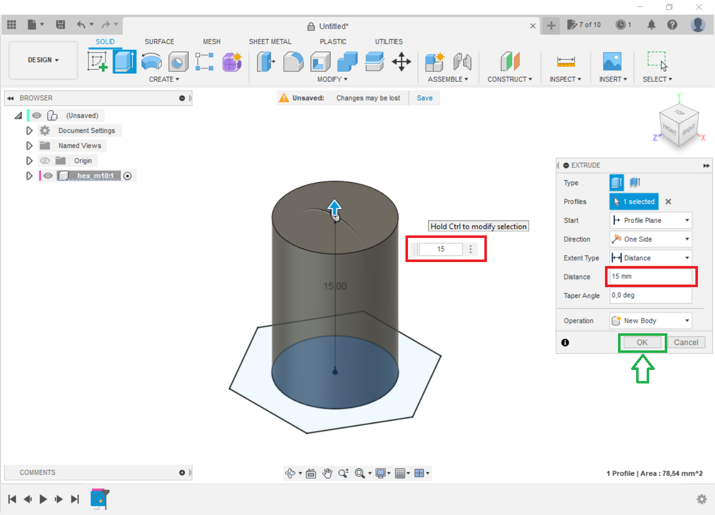
Step 4: Create the screw.
Extrude the circle using the indicated length, and then press OK.
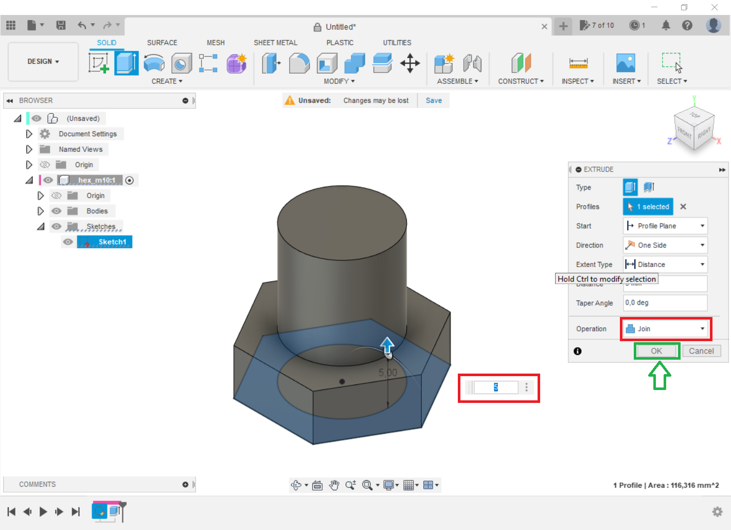
Extrude the hexagon using the indicated length, and then press OK. Don't forget to select the JOIN operation.
-
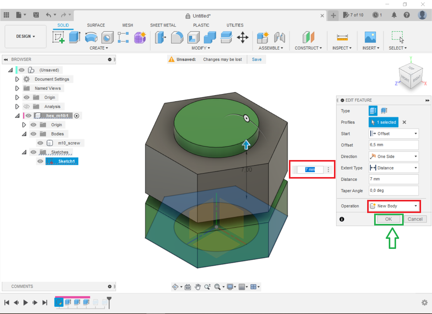
Step 5: Create the nut
Using the same sketch (sketch1), extrude the hexagon using the indicated length, and then press OK. Don't forget to select the NEW BODY operation.
Don't forget to use an offset so that the extruded piece ends up in another place. I used 6.5 mm to make it easier to visualize the subsequent steps.
-
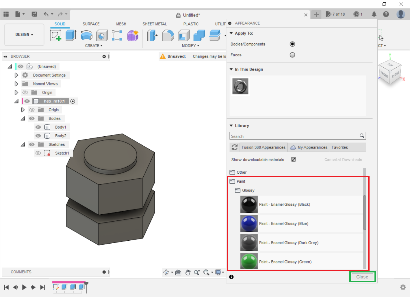
Step 6: Change the appearance
Go to Modify and Change the appearance.
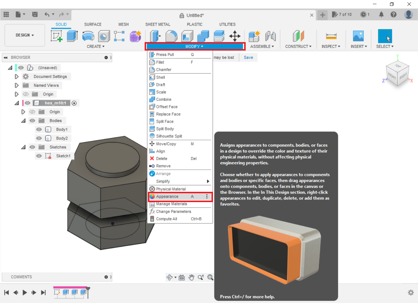
Select the one you like and drag them onto the bodies of the parts, in my case green and yellow. This is done solely for the purpose of facilitating visualization. Then Close.
-
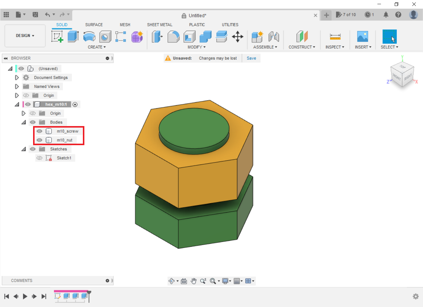
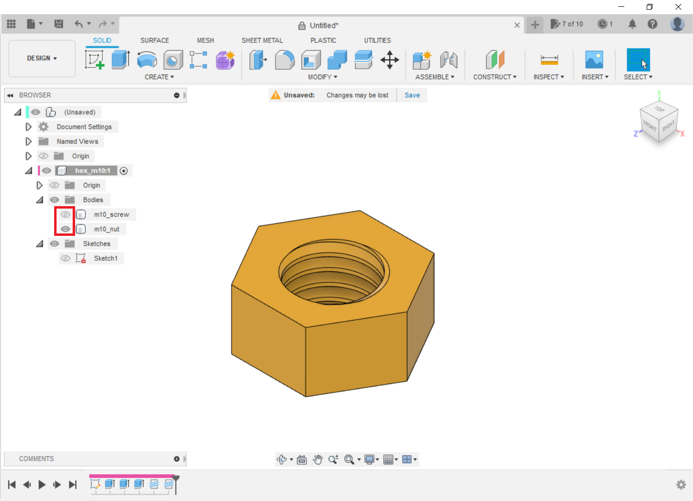
Step 7: Change the names of the bodys
Change the name of the bodies to make them easier to identify.
-
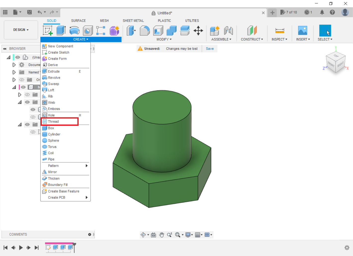
Step 8: Modeling the threads
Select the Create command Threat.
Fusion 360 generates a list with the most approximate thread types to the diameter of the figure that will be modeled with this command. In this case, for a diameter of 10, we will make an M10 thread.
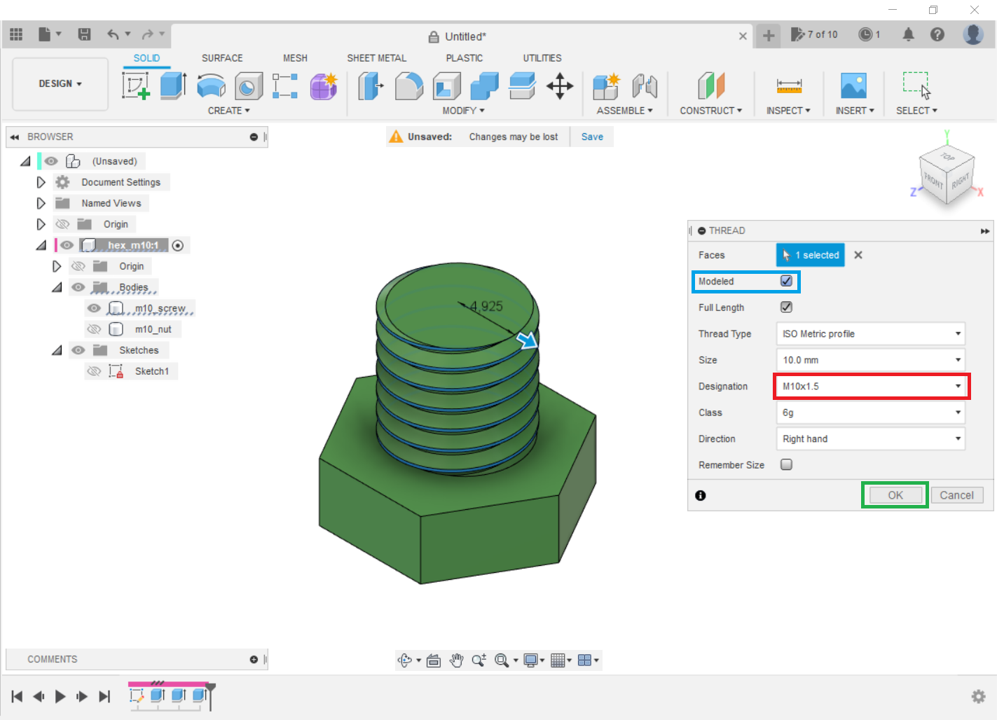
Repeat for the nut. For easy selection, do not forget to turn ON/OFF bodies.
-
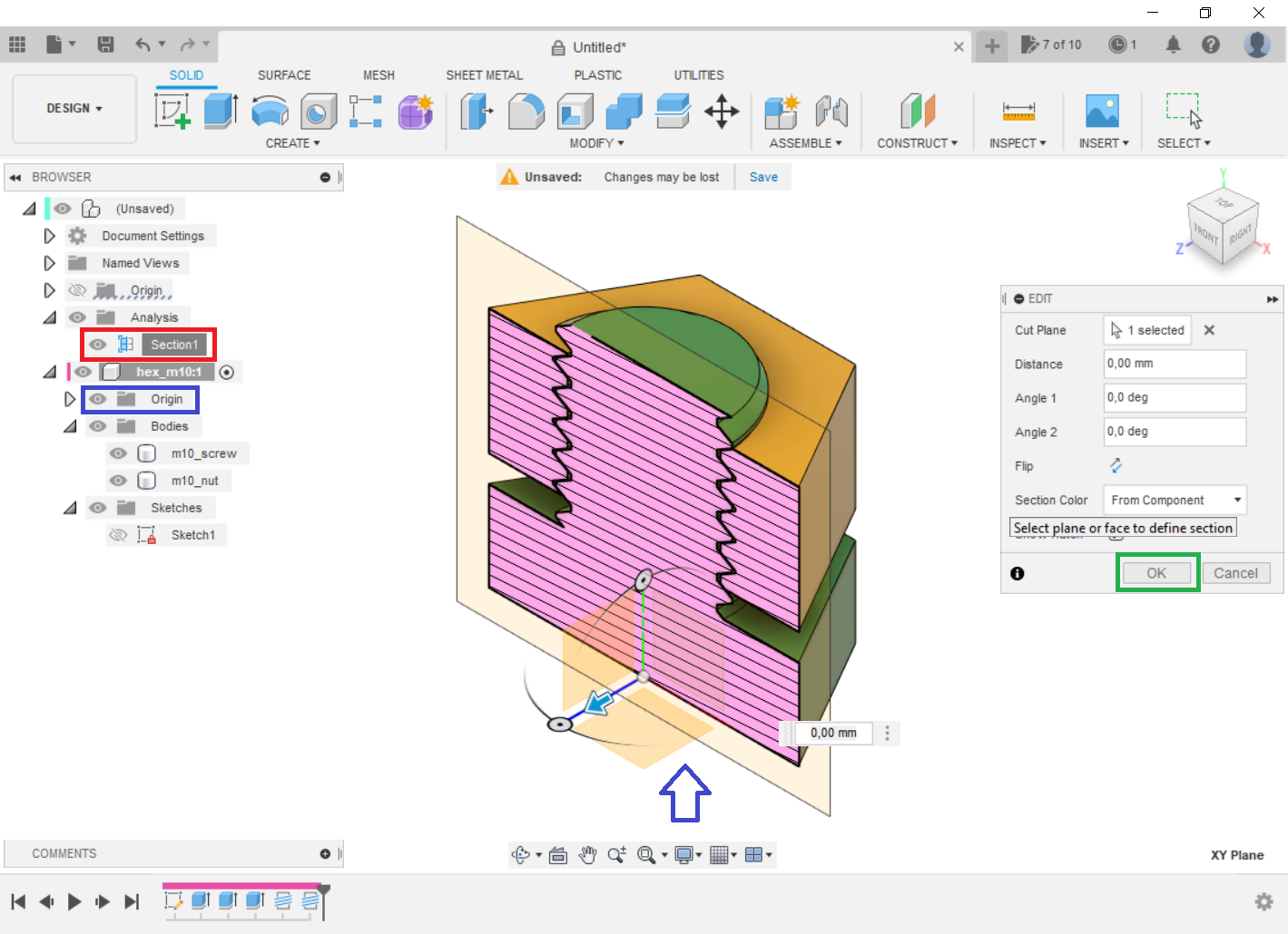
Step 9: Create an inspection plane
In the Inspect section, select Section Analysis.
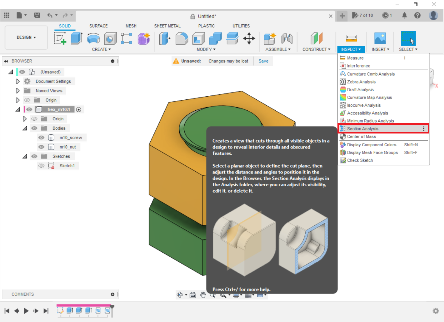
To visualize easily, it is convenient to use an intermediate plane, in this case the XY (to easily locate turn ON the origin). Finally, press OK.
-
Step 10: Adjusting the thread tolerance
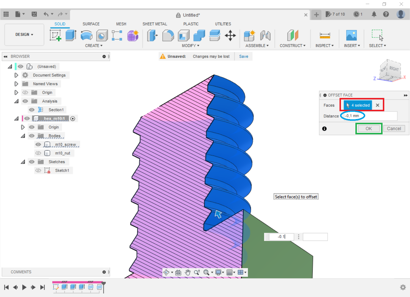
This is the most important step, from this one can obtain a functional thread for 3D printing. In the Modify section, select the Offset Face command.
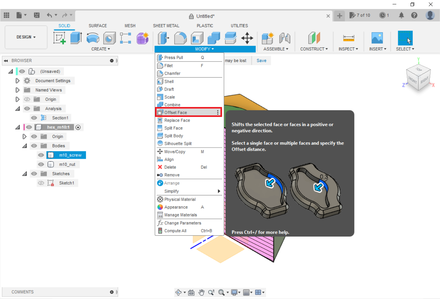
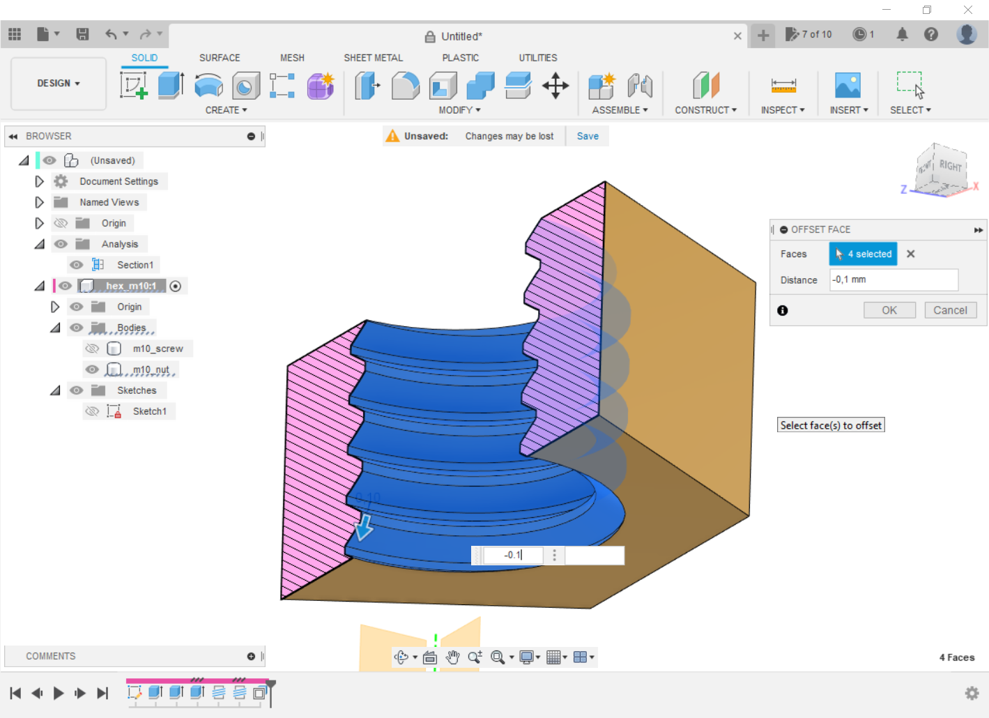
Turn off the nut and select the 4 faces of the screw thread (be careful to select all 4 faces) and assign an offset of -0.1 mm (you can adjust this for your printer tolerance, but 0.1mm usually works very well). Then press OK.
Repeat the procedure for the nut.
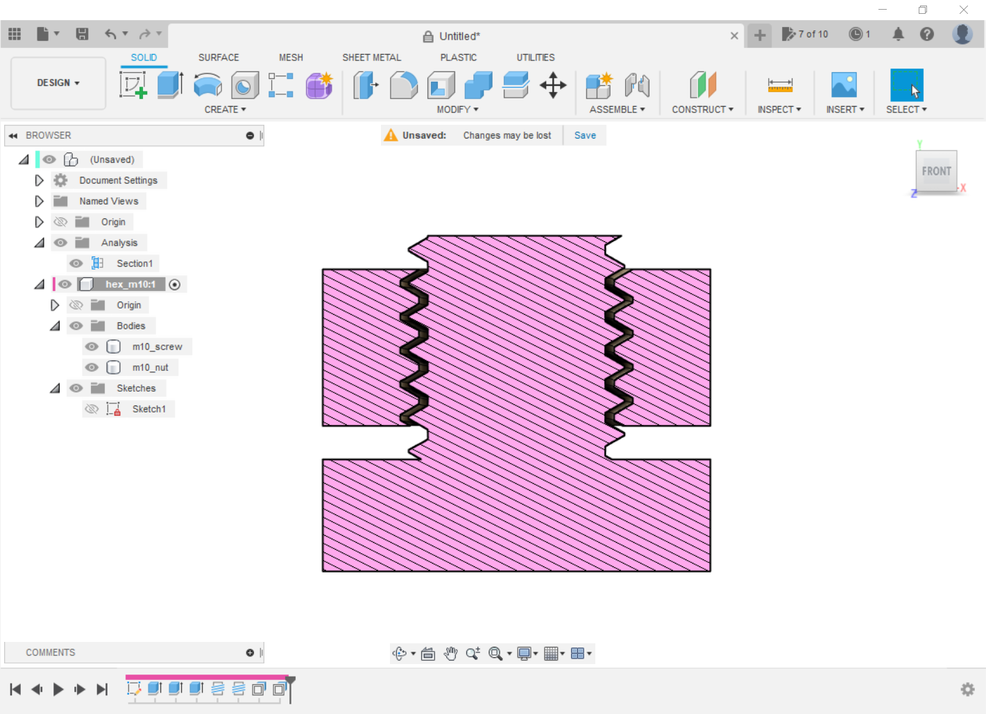
It should result in something like this:
-
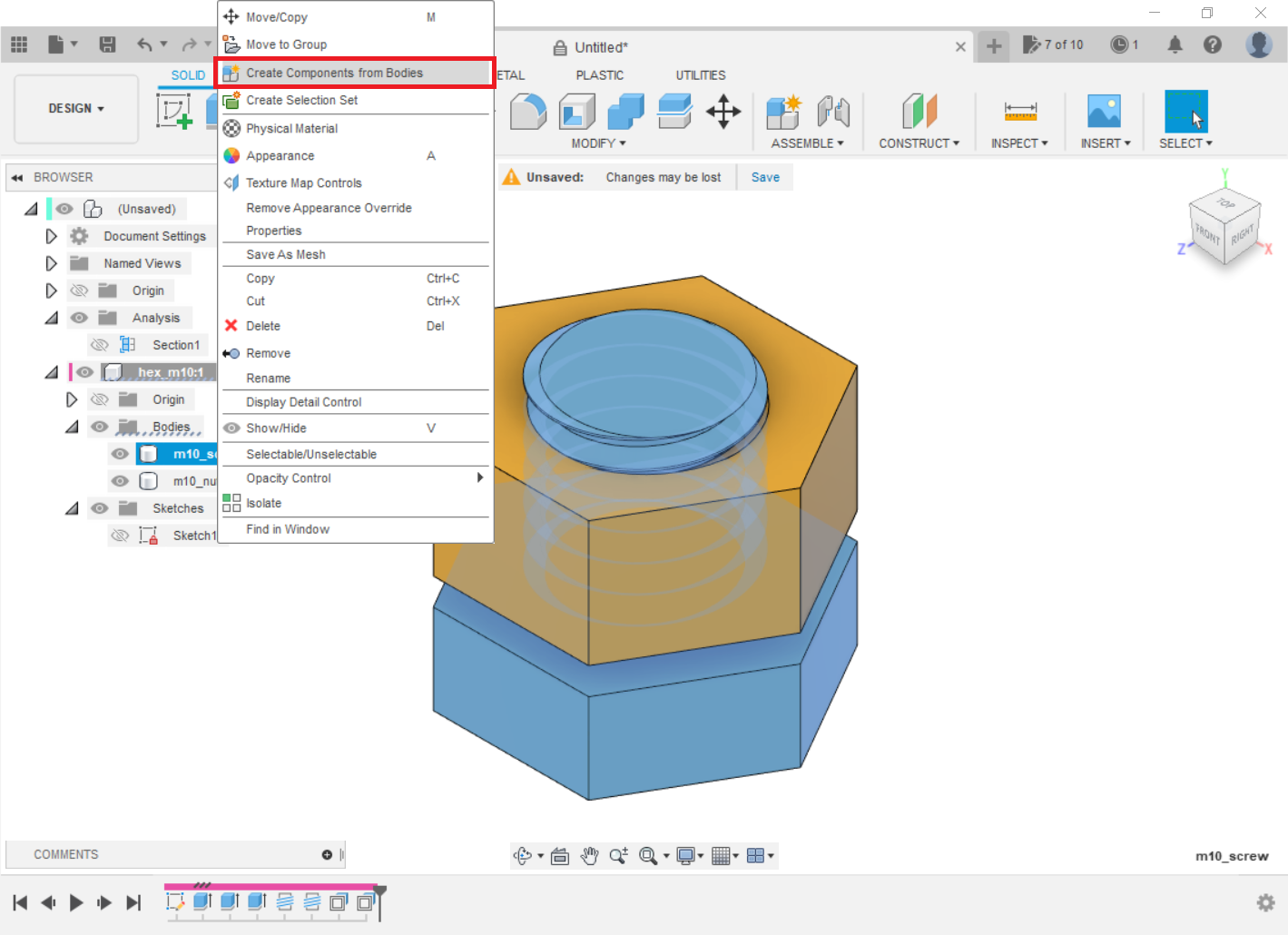
Step 11: Create components
This step is done only to facilitate exporting and mesh generation.
Select the screw and in the Create section, use the Create Component from Body command and repeat for the nut.

-
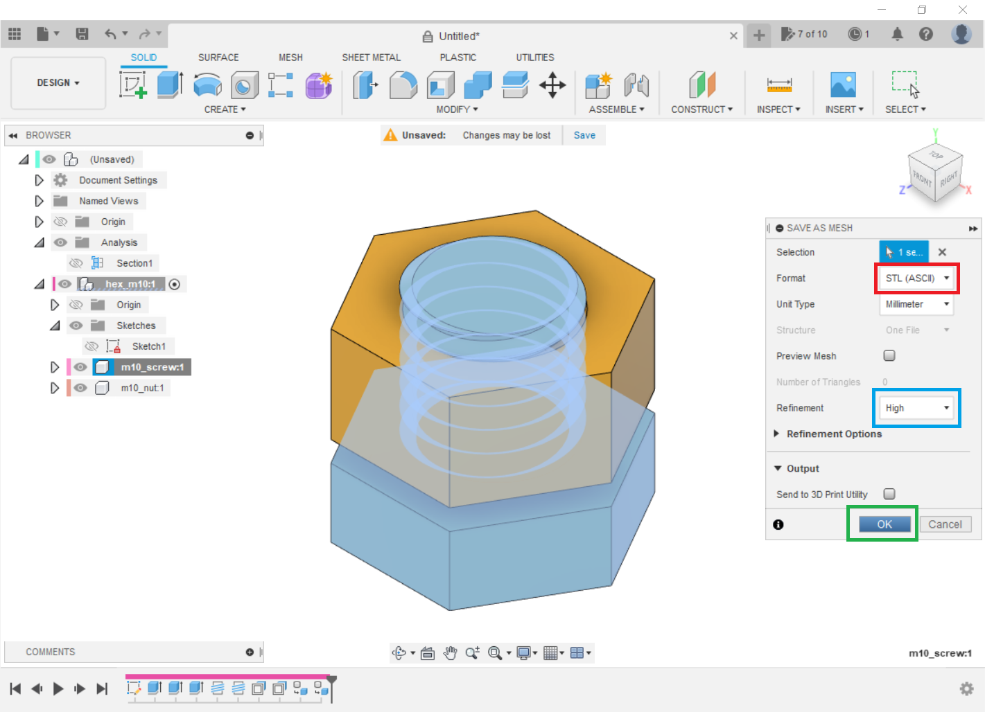
Step 12: Save as mesh
Select the Save as Mesh command.
Be sure to select the STL (ASCII) format and a high mesh refinement. Then press OK.
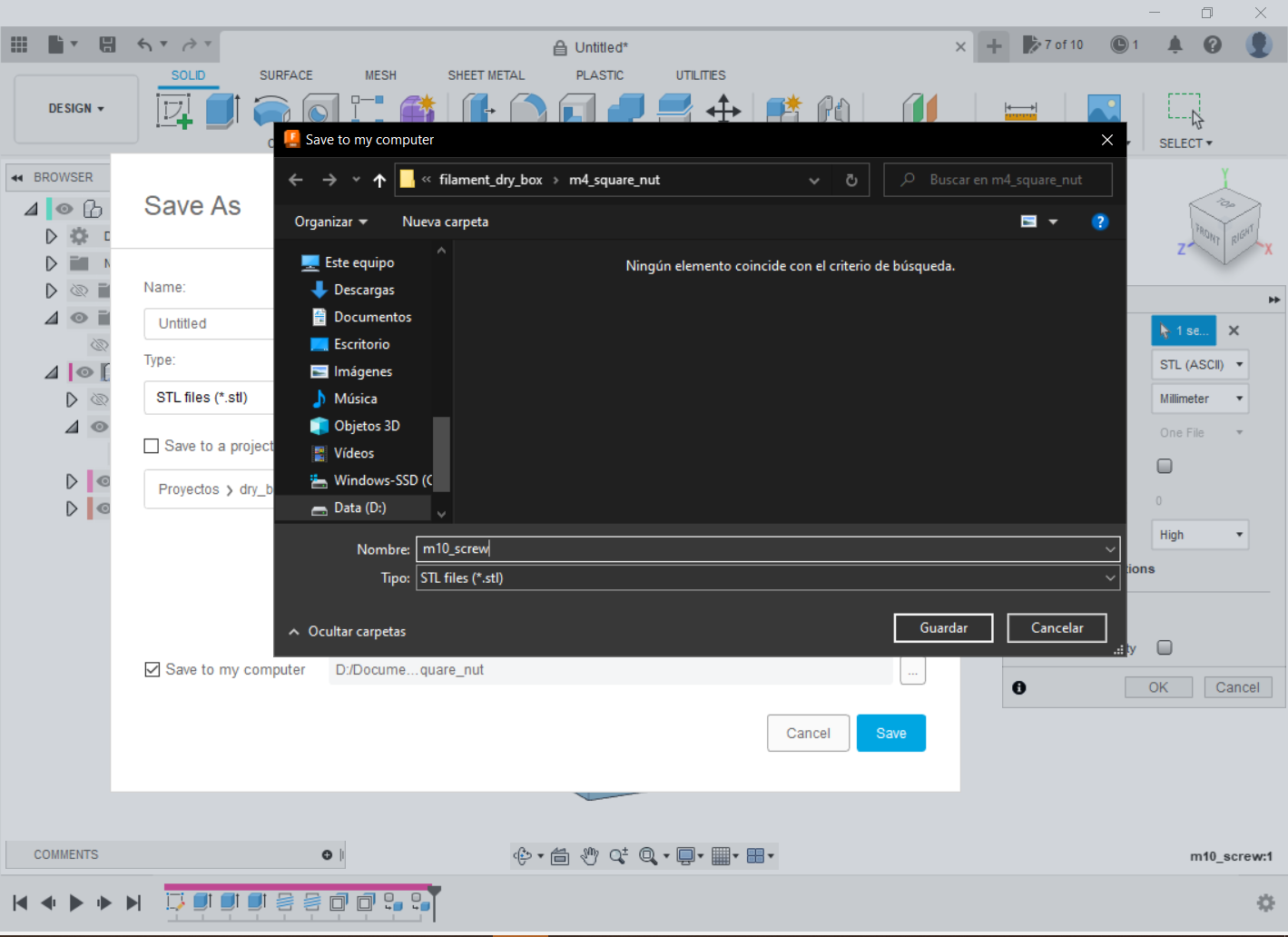
Note: the current version of PrusaSlicer allows the use of .step files, but Ultimaker Cura Slicer does not use this type of file at the moment. For this reason, we export to STL in the example.
-
Step 13: Slicing
Open the slicer software and load the models. As I said, I used PrusaSlicer. Check here for the latest version. You could also use Ultimaker Cura if you prefer, click here.
It is convenient to use low layer heights, as this allows for greater precision in printing. Make sure that the orientation is always as shown, that is, that the thread is printed facing upwards. This allows for the greatest possible precision in the circles that make it up.

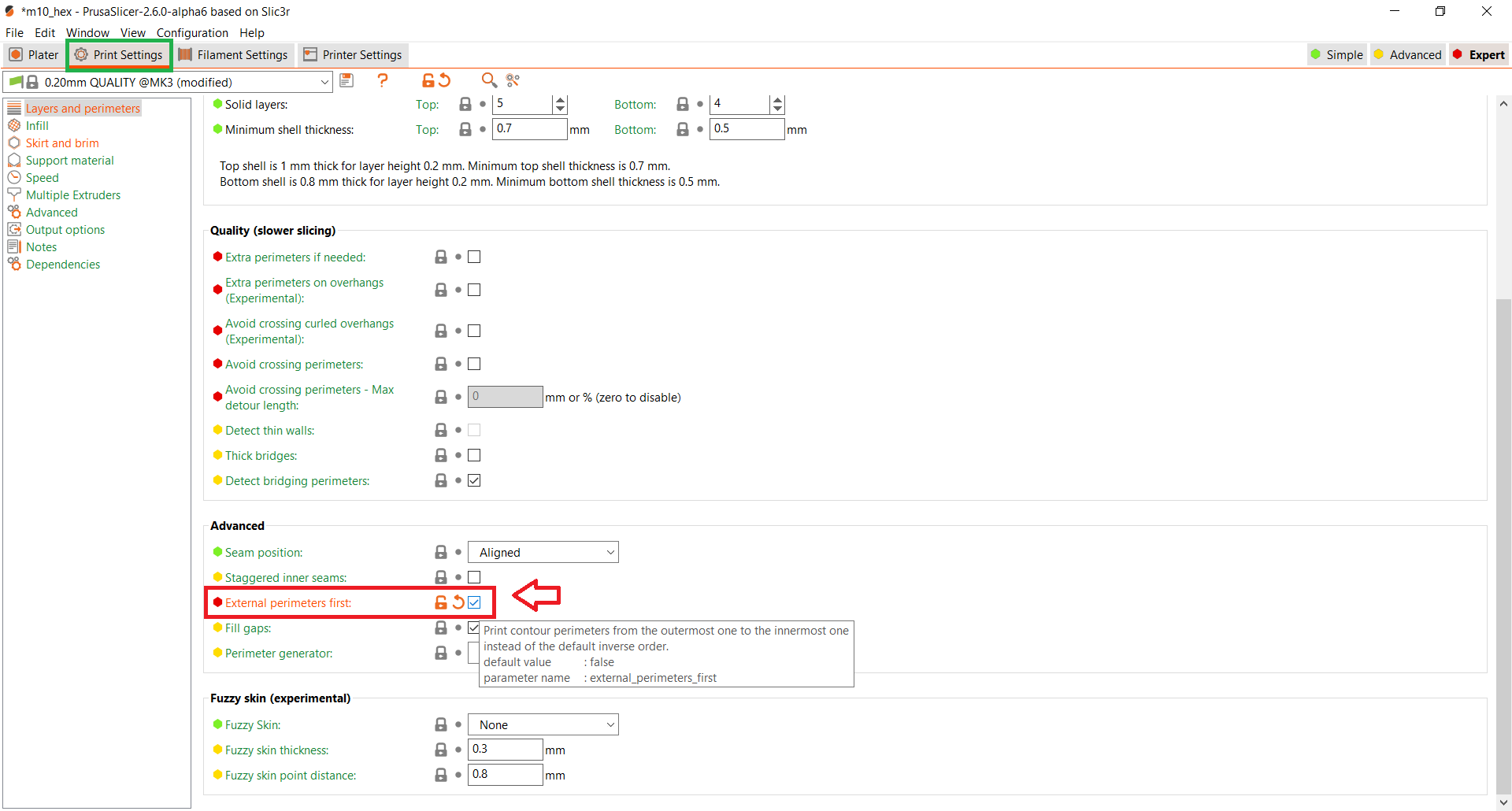
In the Print Settings section, you can also choose to print external perimeters first to improve precision.
PLA is the material with the greatest dimensional tolerance, so while you are learning, it would be beneficial to use it.

-
Step 14: Printing (results)
As mentioned earlier, it may be necessary to adjust the tolerance of the offset. -0.15 or -0.20 should work, but if you need less than this, I think you should review the conditions and settings of your printer.
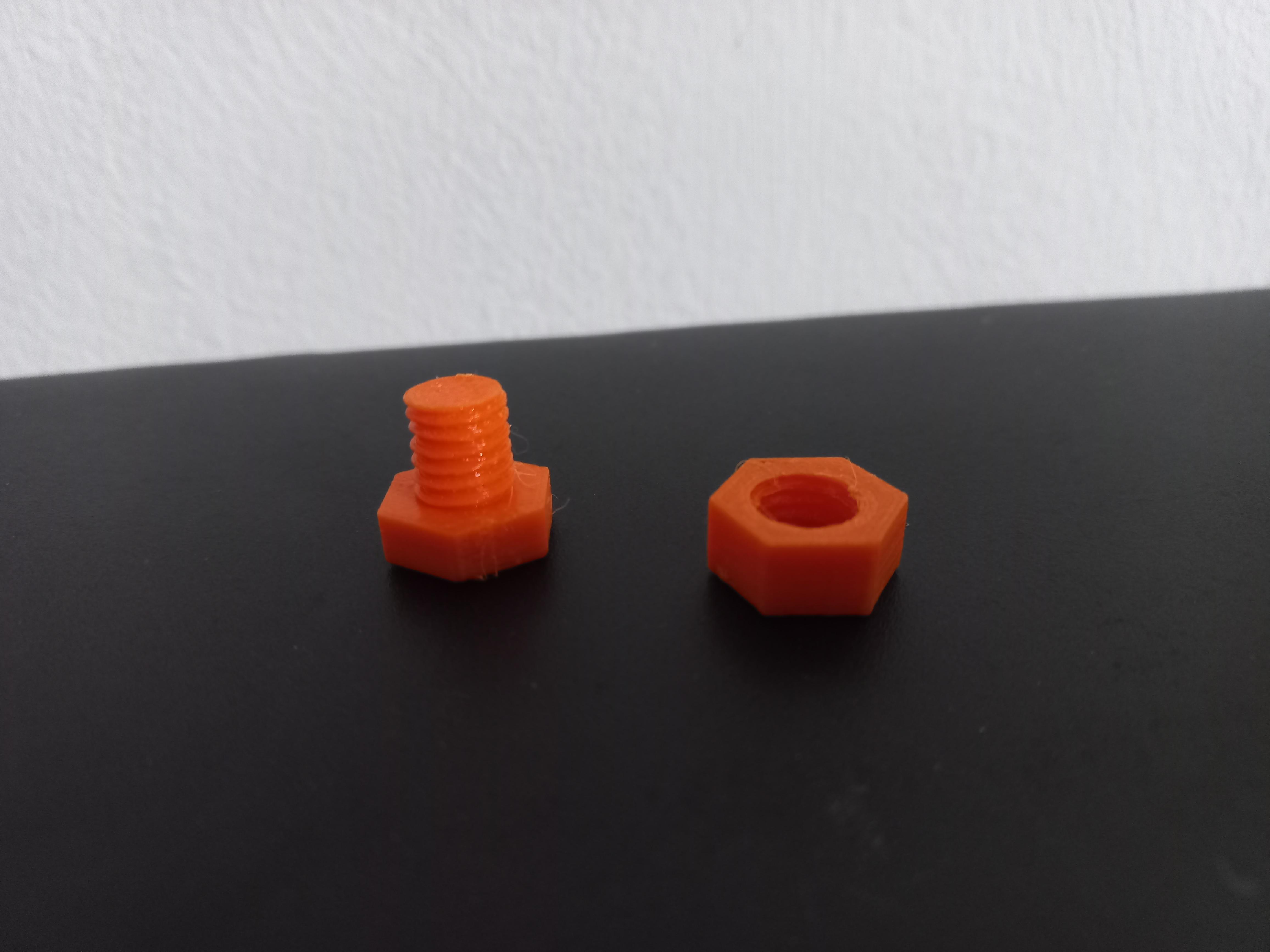
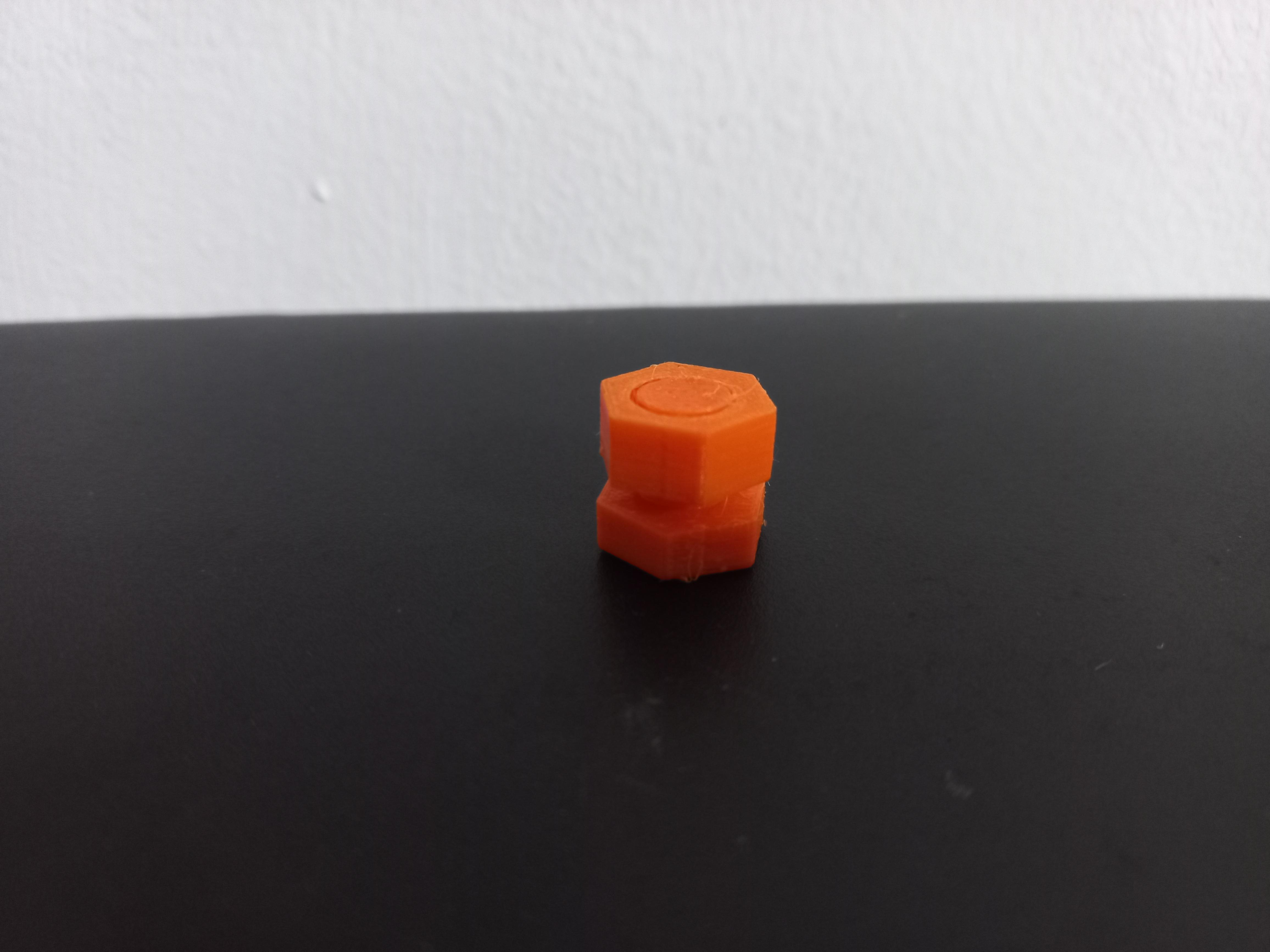
Also, as I said before, for bigger screws you will get better results.
You can find the models I used by clicking here.
I hope you have excellent prints!
