

Parametric Helical Gear

In this tutorial I will show you how to make a parametric helical gear in Catia.
Copyright of Feri Čiradžija mech.ing. (My teacher of technical drawing)
-
Step 1: Creating the parameters
In this first step I will show you how to put your parameters.
So lets star!
First off all open Catia, then go to File-->New-->Part-->call the part "Parametric Helical Gear" -->and click Ok.


After creating the file it would be great to save it, so press Ctrl+S and save it somewhere on your PC.
So now lets start importing the formulas!
Go to f(x) where you will create your parameters.

Click the f(x) tool and a window should pop right in looking like this.

Go to File Type and change it to Hidden Parameters so we can have a better view on the parameters which we are using.

After changing to Hidden parameters lets start making the parameters.
So go to New Parameter of type and a change it from Length to Integer.

Click on Integer and than click on New Parameter of type and Integer.1 should be crated.
Rename the parameter Integer.1 to n (as the number of gears teeth) and set the number of teeth to be 25. And than press apply to confirm your parameter. Everything should look like this:

Here is the list of the other parameters: n (number of teeth)=25
m (module of the gear)=8mm
alpha=20deg
teta (it can be either 8, 12)=8deg
phi=45deg
psi=(360deg/n)
So lets put the parameters right away!
Change the New Parameter of type from Integer to Lenght.

Than click on New Parameter of type and the new parameter should be created and just rename it from Length.1 to m and the measure to 8mm.
It should look like this:

Now lets add the angles. Just change the New parameter of type from Length to Angle.
First lets create the parameter psi. After creating it lets put the formula by clicking Add Formula.

After clicking Add Formula this window will pop out:

Then type in the formula.

You have to put deg so that Catia can know that you are working in degrees.
After typing the formula just click Ok.
And beside the formula should say that its active.
Everything should look like this:

Now type in all of the remaining formulas which are all in Length.
Ro=(m*z/2)
Ra=(Ro+m)
Rb=(Ro*cos(alpha))
Rf=(Ro-1.25*m)
b=(Ro/2)
P=(2*PI*Ro/tan(teta))
After typing in the formulas your done with the parameters.
Everything should look like this!

And beside every formula should be yes.
Now we are done with all of the formulas, so just click ok and the window should close right away.
-
Step 2: Geometry of helical gear
P=2*Ro*PI/tanѲ


Here the height of the gear is equal to P (pitch of the helix)

The gear tooth makes one full revolution if the height is P and here is a good example of that.
-
Step 3: Creating the gear
After showing you how to create the parameters, now we can use them to construct the gear!
So lets begin!
Select the XY plane first so we can create the Sketch of the gears teeth.

After selecting the XY plane click on the Sketch tool.

Your screen should look like this:

Now we are able to make a sketch of the gears tooth.
Now find the circle tool and double-click on it.

The tool should be in orange color, now activate the Construction/Standard Element tool.

Now get to the center and create 4 different circles.
They should look like this:

Now lets constraint those circles by clicking the constraint tool.

Now click an any circle and click on the Radius option:

After selecting radius click anywhere on the screen and the circle should be green.
Than right click o the constraint that you've just made and select the option Edit Formula.

A window should pop in. Now in the blank field type in your parameter for one circle (Ro).

And click ok.
The circle should have a small f(x) icon beside the measure, that means that the measure is used from your formula.

Now repeat the same process for the other 3 circles with the remaining parameters:
Ra, Rb, Rf.
Your circles should look like this:

After making the circles we are going to make 3 lines in this order.
The first lines goes from the center to the furthest circle.

Lets make a constrain from the center to the new line.

Now right click on the constrain and select Edit Formula and put the parameter phi and click Ok.
You should have this:

Now lets make a second line.

We need a constraint that goes from the first line to the second.

Once again we have to use parameters so right click on the constraint and go to Edit Formula and type i (psi/4).
You should get this angle:

Now lets create the third line. In this order!

We must make a constraint between the second and the third line.

Once again right click and choose Edit Formula and type the parameter alpha.

Now go to the circle tool and click the little triangle beneath it. A tool bar should open like this:

Now click the arc tool.

AND THE IMPORTANT THING IS TO DEACTIVATE THE CONSTRUCTION/STANDARD ELEMENT TOOL!!!
Now lets make a semicircle, the center of the pint circle will be the upper point of the third line.
Like this:

Than click on the furthest circle and the closest circle and you should get this:

Now choose the Constraint tool and click on the seconds line upper point and the semicircle and don't click on the screen.

Now right click anywhere and select the command Coincidence.

After that your semicircle should look like this:

If it looks like it GREAT!
Now lets continue.
Find the tool corner.

Click on the Constraint tool and click on your semicircle and the most closest circle to the center of the sketch. You should get this:

Now click create the corner.

Now right click on the corners constraint and go to Edit Formula and type in (0.35*m).
You will get this:

Now hold Ctrl on your keyboard and select the semicircle and corner they should both be orange!

Now lets find the mirror tool.

Click on the mirror tool and choose the center line as a mirror plane.

And you should get this:

Now lets fix the broken down circle by choosing the constraint tool and clicking the corner end point and the broken down end point, like this:

Now right click and choose coincidence and the circle should be all good like this:

As you can see the circle is patched up, if I hadn't patched it up the gear wouldn't work!
So now we need to close up the gear. Choose the arc tool and click at the center of the sketch and the down end points of he gears teeth.

Do the same thing but for the upper part of the gear and keep in mind that everything has to be green!

And here it is, the profile of the gears tooth is finished now we have to exit sketch by pressing the Exit sketch tool. Which looks like this:

Great, once we are done with the gears tooth we can go to Knowledge Inspector Tool.

After opening the Knowledge Inspector tool locate the phi parameter and change it from 45deg to 0deg and click Apply and Ok.

Your gear should look like this now:

Now lets make a line in the middle. Select the YZ plane and open Sketch than select the line tool.

Now take the line and put it i the center.

Choose the Constraint tool and lets constraint the line now. Make sure you press the right click and go to Edit Formula and type in the b parameter. Your sketch should look like this:

If everything is like in the picture you can Exit Sketch.

Now go to -->Start-->Mechanical Design-->Wireframe ad Surface Design.

New tools will appear!
Find the tool Helix which is located t the Splines little triangle:

Now once you've opened Helix a Helix Definition Menu would open.
So choose this as your starting point:

As the axis choose the just created middle line, Type Pitch will be the Parameter P and the Height would be the Parameter b you can add the parameters by right clicking in the box and selecting Edit Formula. Everything needs to look like this:

Do not worry about the red color, if you have type everything right just click Ok and the first helix line is finished, it must look like this:

After we've created the first Helix we need the second Helix, so repeat the same process but only select the other starting Point which will be this one:

Now just slick Ok. And the other Helix is finished!

Now we have to find the Sweep tool. So we can move the downward profile of the gear up. Lets start!

Once we have found the Sweep tool lets open it, locate Subtype and change it to With to guide curves, like this:

As your profile choose the Sketch of the gears tooth, click on the gears tooth:

As your guide curves choose the helix curves that we've just created:

Now go to spine
And right click on the spines box and select the Z axis, THIS IS IMPORTANT because if you would have chosen the middle line the gears top would be defected!

Now don't touch anything else!!! Here is once again how your Sweep Surface Definition should look like:

If everything is correct just click OK. And your gear should look like this:

If it looks like this, GREAT, we are almost done!
Now lets go to Start-->Mechanical Design-->Part Design

Once we are at Part Design we need to find the Close Surface tool (or how we like to call it "cake"). Closed Surface is located in the small triangle beneath the Thick Surface tool:

So click on the Closed Surface tool and if a warning pops out just click OK, its normal, Catia is just informing us what shall happen if we use tool.
Now just select your gear tooth as a Profile to Close and click OK:

And we should get this the gears tooth as an object:

Now we have to get rid of this yellow Sweep color. So click plus on the gear in the tree:

Now locate Sweep.1 and right click it and find Hide/Show:

After clicking Hide/Show the yellow Sweep should disappear and the part should look like this:

If you have gotten the same results, excellent, your gears tooth is finished!
Now all we have to do is make the number of teeth we have which is the n parameter, so lets do it!
We have to find the Circular Pattern tool, which is located at the small triangle beneath the Rectangular Pattern tool.

Click on the tool, in the Instance(s) filled writ click and go to Edit Formula and type n which is the number of teeth. In the Angular Spacing area put the parameter psi.
Now you have to select you Reference Element which will be the center line and Objects need to be Gears tooth.
Here is how it should look like:

If you've gotten everything like in the picture, GREAT, nothing can go wrong now, click OK!
And you should end up with this:

Now we just have to fill in the missing space. So choose the XY plane and click the Sketch tool and create a center circle.

Click on the Constraint tool and click on the circle, than click on the new constraint and go to Edit Formula and type in (Rf*1.001).
And you should have a circle like this:

Now exit Sketch and lets find the Pad tool.

Click on Pad tool and in the Length field right click and go to Edit Formula and type in parameter b.

Just click OK.
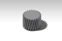
And we should get the GEAR!

And here it is!
A fully working Parametric Gear.
Just to make sure we are going to perform a so called Cross Check.
So all you have to do is go to Knowledge Inspector and change m and n parameters.
Lets do it!

Don't worry about the red color, the changes haven't applied yet that's why.
So lets just click OK.

Here the height is 3.5*Ro.

And there we have it, a Fully working Parametric Helical Gear in Catia!
