

Resize-able part template in Solid Works 2004


This tutorial will show how to create an easily resize-able part template in Solid Works by using a MASTER" sketch along with supplemental sketches and weldment profiles.
I use it for raised panel doors, drawers and cabinetry.
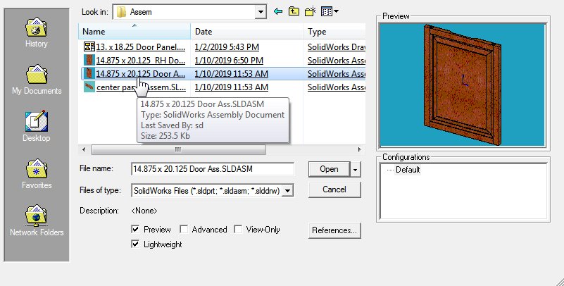
in this tutorial the files I am using are titled "14.875 x 20.125 Door frame.SLDPRT", "13. x 18.25 Door Panel.SLDPRT" which are part of "14.875 x 20.125 Door Ass.SLDASM".
This is my first attempt at doing a tutorial so here goes nothing. { ;-)
File location = 14.875 x 20.125 Door Ass
-
Step 1: Download file
Download the file from my models page( https://grabcad.com/library/14-875-x-20-125-door-ass-1)
-
Step 2: Open assembly
-
Step 3: Open 14.875 x 20.125 Door frame.SLDPRT)

-
Step 4: Edit MASTER sketch
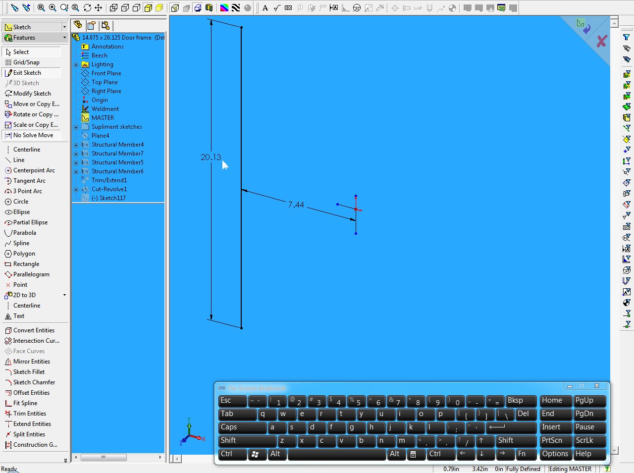
In the master sketch the vertical line controls the height of the door frame. It contains a symmetric relation between the upper point, lower point and the horizontal center line (@ sketch origin) and a line length dimension ( 20.13"). It also contains a distance (7.44 ") relation to the vertical center line (@ sketch origin).
These are the main features in this sketch that will control the height and width of the door frame.
The door panel is controlled the same way using the MASTER sketch in "13. x 18.25 Door Panel.SLDPRT" part
In step 5, I will show how the supplemental sketches come into play.
-
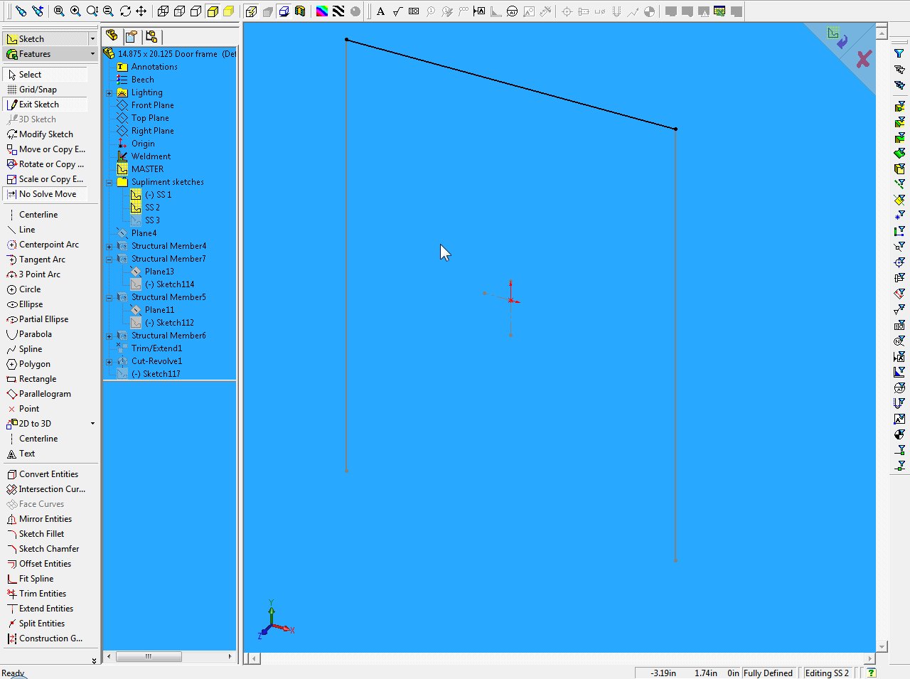
Step 5: Supplemental sketches

Start a new sketch on the same plane as master sketch
draw vertical and horizontal center line @ sketch origin.
Select the master sketch in feature design tree this shows
the line in that sketch. Select the line, hold control button on keyboard
and select the vertical center line and use the mirror command.
Relations should be...Symmetric to center line, a horizontal
relation for the master sketch top point and the supplemental
sketch top point. The bottom two points of both sketches should have
a horizontal relation as well.
There are a total of three supplemental sketches.
The sketches will be used to create a unique weldment "Structural Member". All of the profile sketches (ie.xxx.sldlfp) I created from the my shaper cutting tools. This process will be another tutorial which I have not finished.
-
Step 6: Supplemental sketches (SS 2 & 3)
(SS 2) New sketch.
draw a horizontal line between top points of (master & ss 1) sketch as shown below.
The relations are coincident at the points.
Exit sketch.
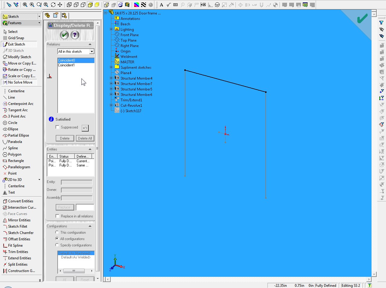
(SS 3) New sketch
draw a horizontal line between bottom points of (master & ss 1) sketch as shown below.
The relations are coincident at the points.
Exit sketch.

After all three supplemental sketches are made add them to new folder and name the folder "supplemental sketches" or whatever you want.
So by creating the relations from SS 1 to MASTER and from SS 2 to SS 1 and from SS 3 TO SS 2 All the supplemental sketches are linked to the MASTER.
Therefore the size of the frame is controlled by only changing the two dimensions in the master sketch.
-
Step 7: Create a Weldment
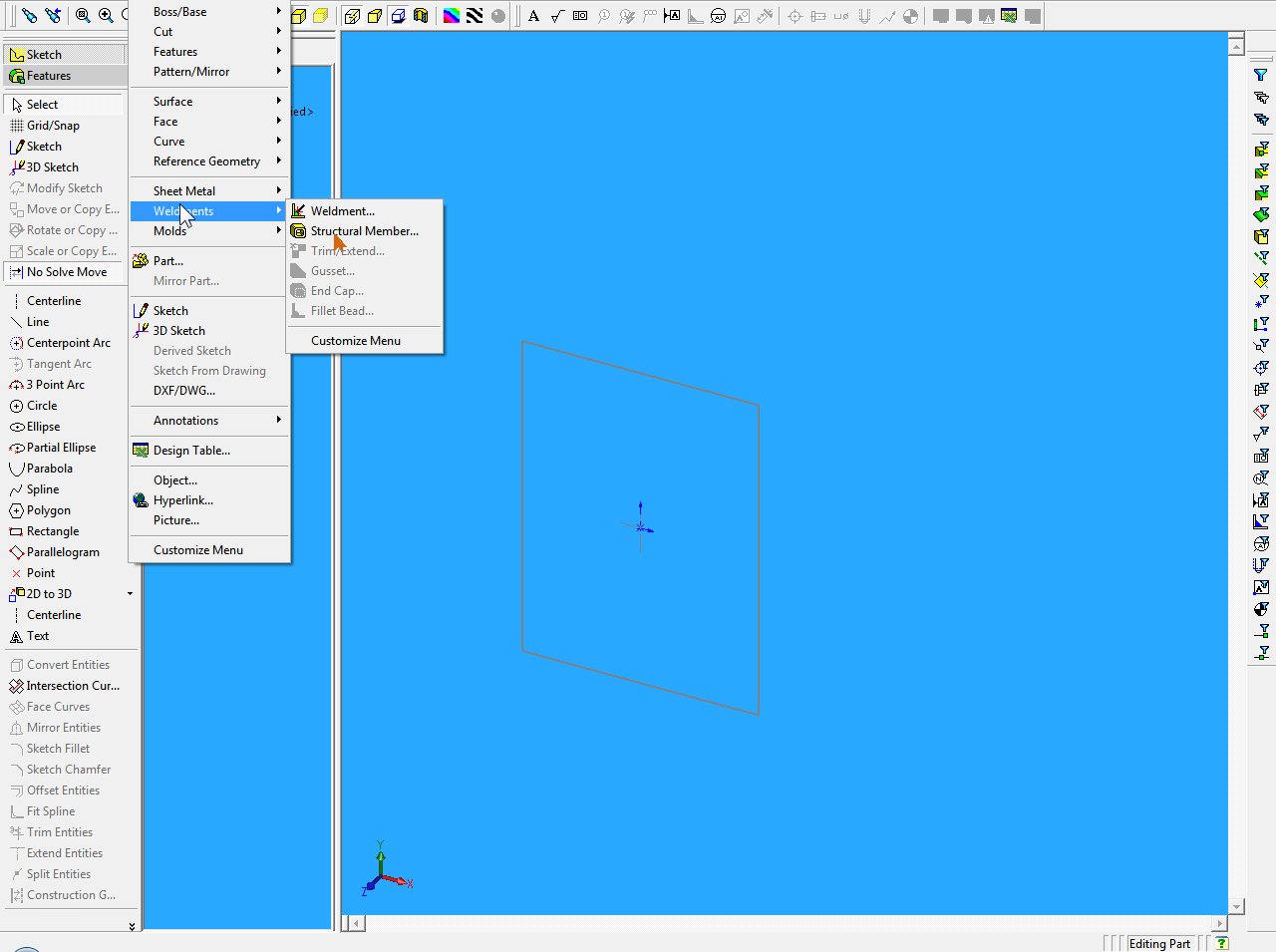
Insert weldments.
Select Structural member.
Select the desired profile from the type and size drop menus and click the line which is in the master sketch. (shown below)
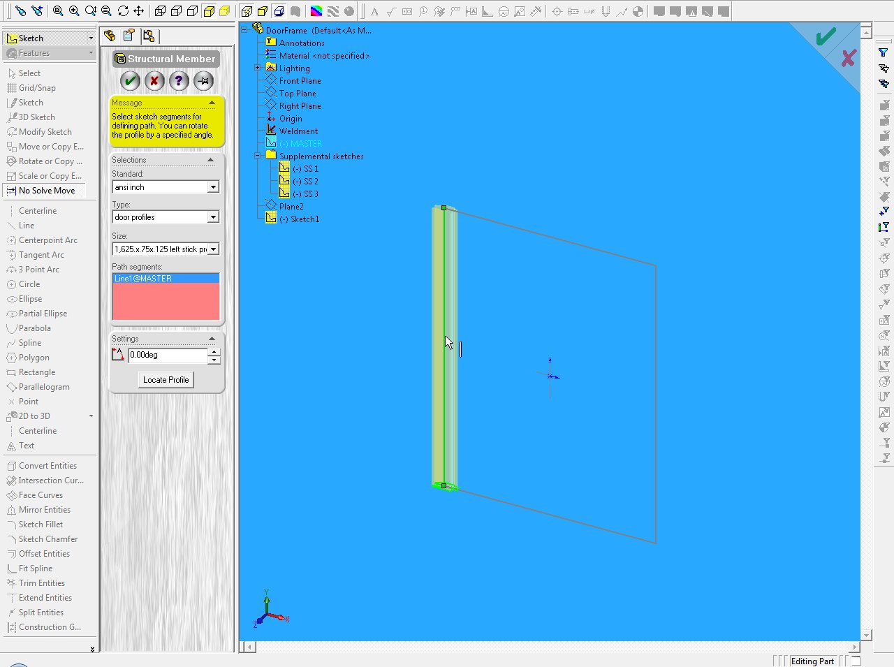
Rotate the profile if needed and locate (orientate) its position on the line as shown below.
Hit Enter or OK.
Fallow the same steps for SS 1, SS 2 and SS 3
I should look something like below.
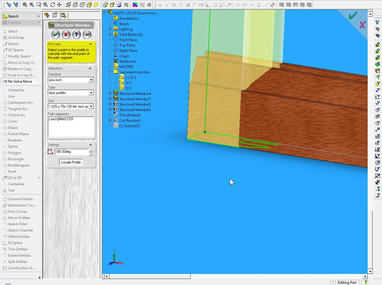
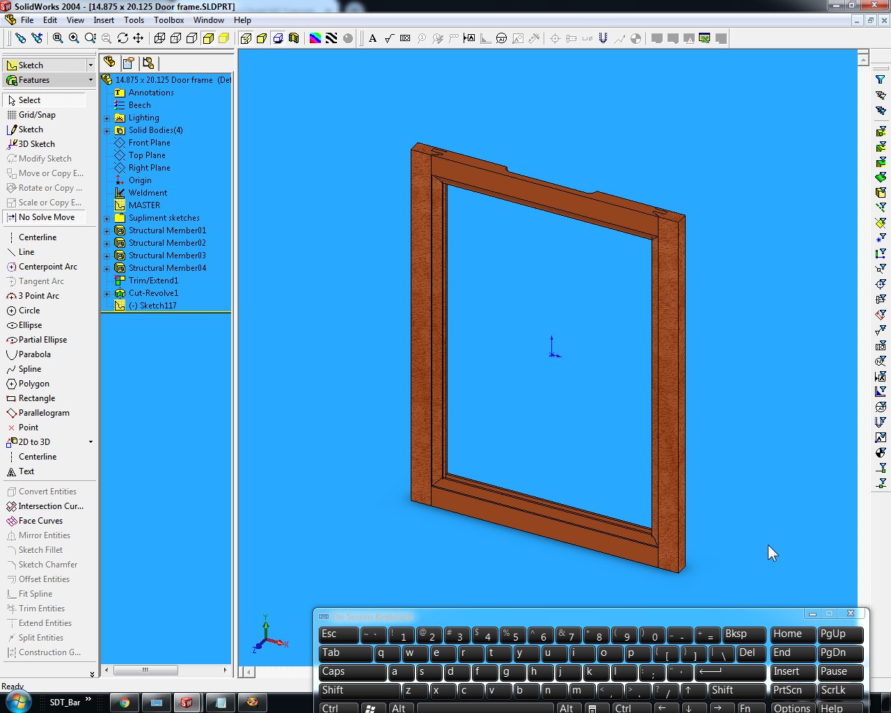
Next is to trim ends of horizontal rails
click Insert > weldments > trim/extend

Select the top and bottom rails as the bodies to be trimmed and

Select the left an right stiles as the trimming boundary.
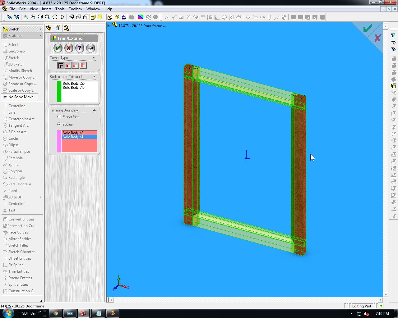
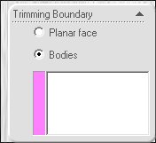
(Make sure the "bodies" is selected in the "trimming boundary" in the "feature manager design tree". (below)
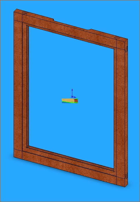
Tada!
-
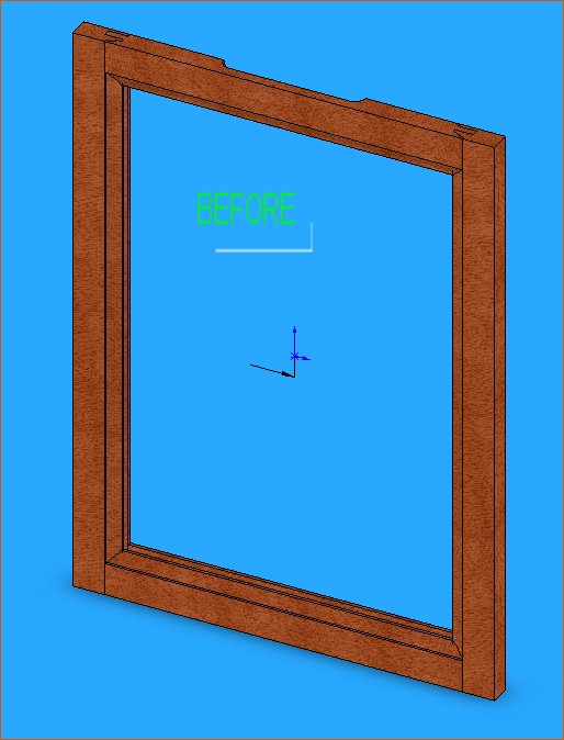
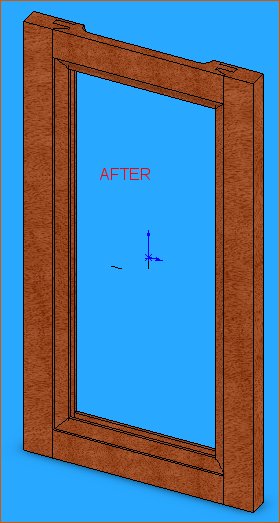
Step 8: Adjust MASTER sketch to resize
Edit the MASTER sketch

Change the line length smaller x 3" ad the distance from center line smaller by 3"
exit sketch.
Should look like below. (before & after)
Next tutorial will be how to create the door panel file.
Please comment, like, hate or whatever.
I appreciate all input.
THANKS !
