

Tutorial for Designing Engine case

This tutorial contains step by step procedure to create engine case using any software, this model especially created using CREO parametric
Click here for my other files
Boolean Operations & Powercopy in CATIA
-
Step 1: Creating Engine case

Step: 1
Open CREO parametric 3.0 click-->File-->New-->Part-->Solid

-
Step 2:
Create sketch as shown below with given dimensions of 20 X 40 mm by selecting Right plane and then click OK

-
Step 3:
Click-->Shapes group-->Extrude option

Extrude the Sketch with extrude depth of 3.5mm in dashboard

-
Step 4:
Select the face marked in green and click-->Datum group -->plane

Create a Datum plane as shown above by entering the translation distance of 3mm

Click Ok
-
Step 5:
Create the sketch as shown below in the newly created DTM1 plane and click ok

-
Step 6:
Extrude the Circle created in previous step to the depth value of 25.5mm

-
Step 7:
Select the top face of the rectangle and create sketch as shown below with specified dimensions and click OK

Note: Use references tools in Setup group to make it simple
-
Step 8:
Extrude the previous created sketch with extrude depth value of 25 mm

-
Step 9:
Select the face shown below and create a sketch with specified dimensions and click OK

-
Step 10:
Create a extrude as shown below with extrude depth of 14 mm

-
Step 11:
Create sketch below with specified dimension by selecting the face as selected below

-
Step 12:
Extrude the sketch created in previous step with depth value of 6mm

-
Step 13:
Create rounds as shown below by selecting the edges with radius of 2mm and click ok

Another Round as shown below with same radius of 2 mm

Create another round on the edge selected before with radius of 1mm

-
Step 14:
Create the sketch as shown below by selecting the mid plane with specified dimensions

Note: create rectangle oriented at 70 degrees from the axis with 7 X 14 mm dimension (use construction lines to make it simple)
-
Step 15:
Create revolve section as shown below with reference the axis and click ok

-
Step 16:
Create sketch as shown below with specified dimensions at the selected faces and extrude with a depth value of 6mm


-
Step 17:
Create the sketches as shown below using references options and using dimension constrains and create extrude up to selected edges as show in images


-
Step 18:
Create rounds with specified dimension r=4mm as shown below

Create rounds at this selected edge with r=2mm

Create rounds as shown below at the selected faces with radius of 3mm

-
Step 19:
Create the sketch as shown below at the right side end face and create a revolve for 180 degrees


And using mirror command mirror the revolve command using the selected plane shown below

-
Step 20:
Create rounds as shown below with specified dimensions on the selected edges with r=2mm

Create rounds r=2.5 mmm at the selected edges as shown below

-
Step 21:
Create sketch as shown below and extrude to a depth value of 9 mm


-
Step 22:
Create the sketch on the same face which you created sketch in the previous step with specified dimensions and create extrude with depth value of 1mm.


-
Step 23:
Create rounds at the corner edges selected below with r=2mm

-
Step 24:
Create a datum plane DTM2 with translation distance of 2mm from the selected face

Create sketch in the previously created plane as shown below and extrude with a depth value of 1mm also create the rounds at the corners with r=2mm as done before


Repeat the step one more time with dimensions given below and create the third fin as shown below


Again repeat the same step with new dimension for the fourth fin


-
Step 25:
Create the sketch as shown below

Extrude the sketch as shown below with depth value 9.22mm

Create an axis pattern as shown below with 4 instances for previously created extrude

-
Step 26:
Create rounds as shown below with r=0.3

Create another rounds at the selected section as shown below with r=0.5mm and repeat the same for all other fins

-
Step 27:
Create the sketch as shown below with specified dimensions on the referenced face below and extrude with a depth value of 12mm


Creates round as shown below with specified dimensions


-
Step 28:
Create sketch as shown below with specified dimensions and remove material using extrude option also create pattern


-
Step 29:
Create sketch at the selected faces as shown below

Now create extrude cut using remove material with depth of 25mm

Now create another sketch as shown below

Extrude it now with a depth value of 0.25mm

Now create round at the selected edge as shown below

-
Step 30:
Create a Datum plane from the selected extrude feature with translation distance of 2mm

Create sketch as shown below use references options in setup group to make it simple

Now extrude with depth value of 1mm and mirror it on other side also pattern it as shown below


Create round as shown below with specified dimensions

Now create sketch as shown below and remove material using extrude tool


Create another sketch as shown below with specified dimension and do extrude cut again using through all option


Create another sketch and do extrude cut with depth value 0f 28mm again as shown below


Create the following sketch and create pattern as shown below


Create rounds on the holes created as shown below

-
Step 31:
Create sketch as shown below and create extrude feature with depth value of


Now remove material up to last using the extrude tool

Create rounds on the edges of the circular section as shown below

Now create sketch at the selected face and create an extrude cut using remove material with depth value of 15mm

Now create sketch as shown below and create extrude cut using remove material also mirror it on other side

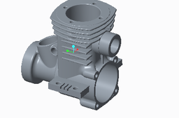
Added some contents to the model further and create an engine case shown below

Final Model

